PROPELLER SHAFT ASSEMBLY (for 2 Joint Type) REASSEMBLY

-
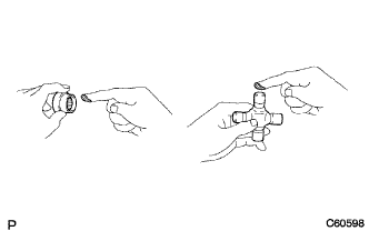
INSTALL UNIVERSAL JOINT SPIDER ASSEMBLY
-
Apply MP grease to a new spider and bearings.
-
Fit the universal joint spider into the flange yoke.
-
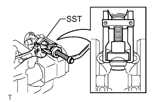
Using SST, install the spider bearings on the spider.
- SST
- 09332-25010
-
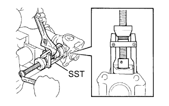
Using SST, adjust both spider bearings so that the snap ring grooves are at the maximum and equal in width.
- SST
- 09332-25010
-
Install 2 new snap rings with the same thickness which allow 0.05 mm (0.002 in.) or less axial play.
Note
Do not reuse the snap rings.
Thickness of snap ring Propeller shaft except No. 37110-25730 Parts No. Thickness
mm (in.)
Mark 90520-25039 2.28 to 2.30
(0.0898 to 0.0906)
1 90520-25040 2.30 to 2.32
(0.0906 to 0.0913)
2 90520-25041 2.32 to 2.34
(0.0913 to 0.0921)
- 90520-25042 2.34 to 2.36
(0.0921 to 0.0929)
Brown 90520-25043 2.36 to 2.38
(0.0929 to 0.0937)
Blue 90520-25044 2.38 to 2.40
(0.0937 to 0.0945)
6 90520-25045 2.40 to 2.42
(0.0945 to 0.0953)
7 90520-25046 2.42 to 2.44
(0.0953 to 0.0961)
8 90520-25047 2.44 to 2.46
(0.0961 to 0.0969)

90520-25048 2.46 to 2.48
(0.0969 to 0.0976)
10 90520-25049 2.48 to 2.50
(0.0976 to 0.0984)
A 90520-25050 2.50 to 2.52
(0.0984 to 0.0992)
B 90520-25051 2.52 to 2.54
(0.0992 to 0.1000)
C 90520-25052 2.54 to 2.56
(0.1000 to 0.1008)
D 90520-25053 2.56 to 2.58
(0.1008 to 0.1016)
E 90520-25054 2.18 to 2.20
(0.0858 to 0.0866)
J 90520-25055 2.20 to 2.22
(0.0866 to 0.0874)
K 90520-25056 2.22 to 2.24
(0.0874 to 0.0882)
F 90520-25057 2.24 to 2.26
(0.0882 to 0.0890)
G 90520-25058 2.26 to 2.28
(0.0890 to 0.0898)
H Propeller shaft No. 37110-25730 Parts No. Thickness
mm (in.)
Mark 90520-29024 1.985 to 2.015
(0.0782 to 0.0793)
- 90520-29025 2.015 to 2.045
(0.0793 to 0.0805)
Light Brown 90520-29026 2.045 to 2.075
(0.0805 to 0.0817)
Blue 90520-29027 2.075 to 2.105
(0.0817 to 0.0829)
- 90520-29039 1.98 to 2.00
(0.0780 to 0.0787)
1 90520-29040 2.00 to 2.02
(0.0787 to 0.0795)
2 90520-29041 2.02 to 2.04
(0.0795 to 0.0803)
3 90520-29042 2.04 to 2.06
(0.0803 to 0.0811)
4 90520-29043 2.06 to 2.08
(0.0811 to 0.0819)
5 90520-29044 2.08 to 2.10
(0.0819 to 0.0827)
6 90520-29045 2.10 to 2.12
(0.0827 to 0.0835)
7 90520-29046 2.12 to 2.14
(0.0835 to 0.0843)
8 90520-29047 2.14 to 2.16
(0.0843 to 0.0850)
90520-29048 2.16 to 2.18
(0.0850 to 0.0858)
10 Tech Tips
Snap rings with the same thickness should be used on both sides.
-
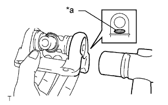
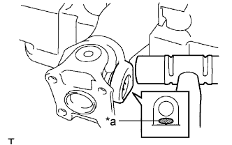
Text in Illustration *a Hammering Point Using a hammer, tap the flange yoke until there is no clearance between the spider bearing outer race and snap ring.
Note
Do not damage the flange yoke.
-
Align the matchmarks on the propeller shaft and flange yoke.
-
Using SST, adjust both spider bearings so that the snap ring grooves are at the maximum and equal in width.
- SST
- 09332-25010
-
Install 2 new snap rings with the same thickness which allow 0.05 mm (0.002 in.) or less axial play.
Note
Do not reuse the snap rings.
Thickness of snap ring Propeller shaft except No. 37110-25730 Parts No. Thickness
mm (in.)
Mark 90520-25039 2.28 to 2.30
(0.0898 to 0.0906)
1 90520-25040 2.30 to 2.32
(0.0906 to 0.0913)
2 90520-25041 2.32 to 2.34
(0.0913 to 0.0921)
- 90520-25042 2.34 to 2.36
(0.0921 to 0.0929)
Brown 90520-25043 2.36 to 2.38
(0.0929 to 0.0937)
Blue 90520-25044 2.38 to 2.40
(0.0937 to 0.0945)
6 90520-25045 2.40 to 2.42
(0.0945 to 0.0953)
7 90520-25046 2.42 to 2.44
(0.0953 to 0.0961)
8 90520-25047 2.44 to 2.46
(0.0961 to 0.0969)
90520-25048 2.46 to 2.48
(0.0969 to 0.0976)
10 90520-25049 2.48 to 2.50
(0.0976 to 0.0984)
A 90520-25050 2.50 to 2.52
(0.0984 to 0.0992)
B 90520-25051 2.52 to 2.54
(0.0992 to 0.1000)
C 90520-25052 2.54 to 2.56
(0.1000 to 0.1008)
D 90520-25053 2.56 to 2.58
(0.1008 to 0.1016)
E 90520-25054 2.18 to 2.20
(0.0858 to 0.0866)
J 90520-25055 2.20 to 2.22
(0.0866 to 0.0874)
K 90520-25056 2.22 to 2.24
(0.0874 to 0.0882)
F 90520-25057 2.24 to 2.26
(0.0882 to 0.0890)
G 90520-25058 2.26 to 2.28
(0.0890 to 0.0898)
H Propeller shaft No. 37110-25730 Parts No. Thickness
mm (in.)
Mark 90520-29024 1.985 to 2.015
(0.0782 to 0.0793)
- 90520-29025 2.015 to 2.045
(0.0793 to 0.0805)
Light Brown 90520-29026 2.045 to 2.075
(0.0805 to 0.0817)
Blue 90520-29027 2.075 to 2.105
(0.0817 to 0.0829)
- 90520-29039 1.98 to 2.00
(0.0780 to 0.0787)
1 90520-29040 2.00 to 2.02
(0.0787 to 0.0795)
2 90520-29041 2.02 to 2.04
(0.0795 to 0.0803)
3 90520-29042 2.04 to 2.06
(0.0803 to 0.0811)
4 90520-29043 2.06 to 2.08
(0.0811 to 0.0819)
5 90520-29044 2.08 to 2.10
(0.0819 to 0.0827)
6 90520-29045 2.10 to 2.12
(0.0827 to 0.0835)
7 90520-29046 2.12 to 2.14
(0.0835 to 0.0843)
8 90520-29047 2.14 to 2.16
(0.0843 to 0.0850)
90520-29048 2.16 to 2.18
(0.0850 to 0.0858)
10 Tech Tips
Snap rings with the same thickness should be used on both sides.
-
Text in Illustration *a Hammering Point Using a hammer, tap the flange yoke until there is no clearance between the spider bearing outer race and snap ring.
Note
Do not damage the flange yoke.
-
-
INSPECT UNIVERSAL JOINT SPIDER ASSEMBLY
-
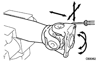
Check that the spider bearing rotates smoothly.
-
Check that there is no play in the spider bearing.
-
Using a spring tension gauge, hang the hook of the spring tension gauge in a bolt hole of the flange yoke and measure the rotating force.
Standard 1.1 N*m (11.2 kgf*cm, 9.7 in.*lbf) or less Note
-
Measurement of rotating force should be done at 2 positions for each universal joint by 90° in opposite directions (flange yoke side and end yoke side).
-
When it exceeds the standard, use a thinner snap ring.
-
-
-
INSPECT PROPELLER SHAFT ASSEMBLY
Tech Tips
When replacing the spider bearing, make sure that the grease fitting hole is facing in the direction shown in the illustration.
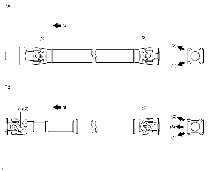
Text in Illustration *A for G54 and R351 Manual Transmission *B for R451 and R452 Manual Transmission *a Front Side - -