PROPELLER SHAFT ASSEMBLY (for 2 Joint Type) REMOVAL

-
REMOVE PROPELLER SHAFT ASSEMBLY (for G54 and R351 Manual Transmission)
-
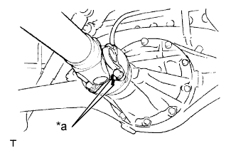
Place matchmarks on the propeller shaft flange and differential flange.
Text in Illustration *a Matchmark -
Remove the 4 nuts, 4 bolts and 4 washers.
-
Remove the propeller shaft assembly.
-
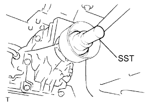
Insert SST into the extension housing to prevent oil leakage.
Note
Do not damage the oil seal.
-
Use the following SST for the R351 manual transmission.
- SST
- 09325-40010
-
Use the following SST for the G54 manual transmission.
- SST
- 09325-20010
-
-
-
REMOVE PROPELLER SHAFT ASSEMBLY (for R451 and R452 Manual Transmission)
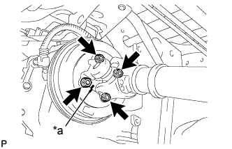
Text in Illustration *a Matchmark
-
Place matchmarks on the propeller shaft flange and parking brake drum.
-
Remove the 4 nuts and 4 washers.
-
Text in Illustration *a Matchmark Place matchmarks on the propeller shaft flange and differential flange.
-
Remove the 4 nuts, 4 bolts and 4 washers.
-
Remove the propeller shaft assembly.
-
-
INSPECT PROPELLER SHAFT ASSEMBLY
-
Visually check the propeller shaft assembly.
-
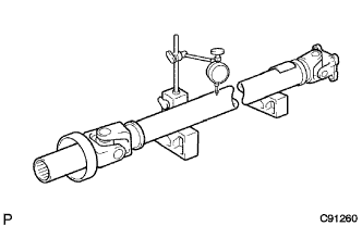
Using a dial indicator, inspect the runout of the shaft tube.
Standard Shaft Tube Length Maximum Runout 800 mm (31.50 in.) or more 0.4 mm (0.016 in.) Less than 800 mm (31.50 in.) 0.3 mm (0.012 in.) If the shaft runout is greater than the maximum, replace the propeller shaft assembly.
-
-
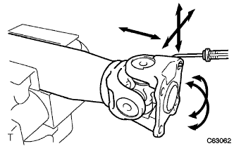
INSPECT UNIVERSAL JOINT SPIDER ASSEMBLY
-
Check that the spider bearing rotates smoothly.
-
Check that there is no play in the spider bearing.
-
Using a spring tension gauge, hang the hook of the spring tension gauge in a bolt hole of the flange yoke and measure the rotating force.
Standard 1.1 N*m (11.2 kgf*cm, 9.7 in.*lbf) or less Note
-
Measurement of the rotating force should be done at 2 positions for each universal joint by 90° in opposite directions (flange yoke side and end yoke side).
-
When it exceeds the standard, use a thinner snap ring.
-
-