DIFFERENTIAL CARRIER ASSEMBLY (for 4 Pinion Gear Type) REASSEMBLY

-
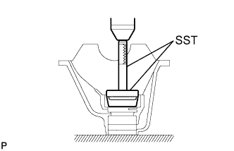
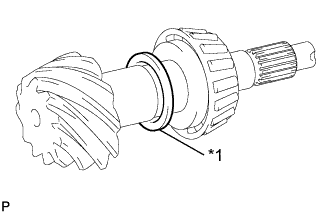
INSTALL REAR DIFFERENTIAL DUST DEFLECTOR
-
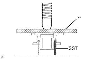
Text in Illustration *1 Plate Using a press, install the rear differential dust deflector.
Note
Be careful not to damage the dust deflector.
- SST
- 09631-12090
-
-
INSTALL REAR DIFFERENTIAL CASE SUB-ASSEMBLY
-
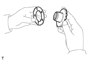
Install the rear differential side gear thrust washer to the rear differential side gear.
-
Install the rear differential pinion thrust washer and rear differential pinion to the rear differential spider.
-
Fix the differential case RH.
-
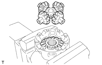
Install the rear differential side gear and rear differential spider to the differential case RH.
-
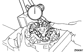
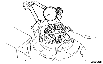
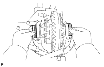
Using a dial indicator, measure the differential case RH side backlash while holding the pinion toward the case.
Standard backlash 0.02 to 0.20 mm (0.0008 to 0.008 in.) -
Remove the rear differential spider from the differential case RH.
-
Install the rear differential side gear and rear differential spider to the differential case LH.
-
Using a dial indicator, measure the differential case RH side backlash while holding the pinion toward the case.
Standard backlash 0.02 to 0.20 mm (0.0008 to 0.008 in.) If the backlash is not within the specification, install the 2 side gear thrust washers with different thickness.
Thrust washer thickness Thickness mm (in.) Thickness mm (in.) 1.53 to 1.57 (0.0602 to 0.0618) 1.83 to 1.87 (0.0720 to 0.0736) 1.58 to 1.62 (0.0622 to 0.0638) 1.88 to 1.92 (0.0740 to 0.0756) 1.63 to 1.67 (0.0641 to 0.0657) 1.93 to 1.97 (0.0760 to 0.0776) 1.68 to 1.72 (0.0661 to 0.0677) 1.98 to 2.02 (0.0780 to 0.0795) 1.73 to 1.77 (0.0681 to 0.0697) 2.03 to 2.07(0.0800 to 0.0815) 1.78 to 1.82 (0.0700 to 0.0717) 2.08 to 2.12 (0.0819 to 0.0835) -
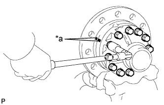
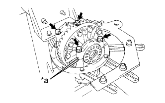
Text in Illustration *a Matchmark Align the matchmarks and assemble the RH and LH cases.
-
Using a plastic hammer, install the differential case.
-
Install the 12 bolts.
- Torque:
- 78.5 N*m { 800 kgf*cm, 58 ft.*lbf }
-
-
INSTALL DIFFERENTIAL RING GEAR
-
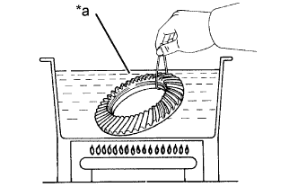
Text in Illustration *a Boiling Water Clean the contact surfaces of the differential case and ring gear.
-
Heat the ring gear approx. 100°C (212°F) in the boiling water.
-
Carefully take the ring gear out of the boiling water.
-
After the moisture on the ring gear has completely evaporated, quickly install the ring gear to the differential case.
-
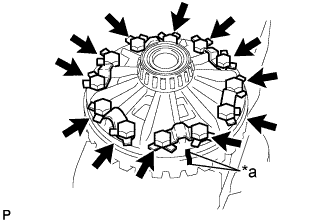
Text in Illustration *a Matchmark Align the matchmarks on the ring gear and differential case.
-
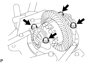
Temporarily install 6 new lock plates and 12 bolts.
-
After the ring gear cools down enough, torque the 12 bolts uniformly at a time.
- Torque:
- 162 N*m { 1652 kgf*cm, 119 ft.*lbf }
-
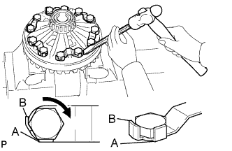
Using a chisel and a hammer, stake the 6 lock plates.
Tech Tips
Stake one claw so that it is flush with the flat surface of the bolt.
For the claw contacting the protruding portion of the bolt, stake only the half on the tightening side.
-
-
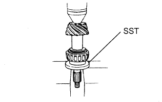
INSTALL REAR DIFFERENTIAL CASE BEARING
-
Using SST and a press, install the bearing on the differential case.
- SST
- 09316-20011
- 09950-60010 ( 09951-00500 )
-
-
INSPECT DIFFERENTIAL RING GEAR RUNOUT
-
Install the differential case on the carrier, and install the 2 adjusting nuts so that there is no play in the bearing.
-
Install the 2 bearing caps with the 4 bolts.
- Torque:
- 196 N*m { 1997 kgf*cm, 145 ft.*lbf }
-
Using a dial indicator, measure the runout of the ring gear.
Maximum runout 0.01 mm (0.00039 in.) -
Remove the 2 bearing caps, 2 adjusting nuts and differential case.
-
-
INSTALL REAR DRIVE PINION FRONT TAPERED ROLLER BEARING
-
Using SST and a press, install the front bearing (outer race) to the carrier.
- SST
- 09950-60020 ( 09951-00780 )
- 09950-70010 ( 09951-07150 )
-
-
INSTALL REAR DRIVE PINION REAR TAPERED ROLLER BEARING
-
Using SST and a press, install the rear bearing (outer race) to the carrier.
- SST
- 09950-60020 ( 09951-01030 )
- 09950-70010 ( 09951-07150 )
-
-
INSTALL REAR DRIVE PINION REAR TAPERED ROLLER BEARING
-
Install the removed plate washer on the drive pinion.
-
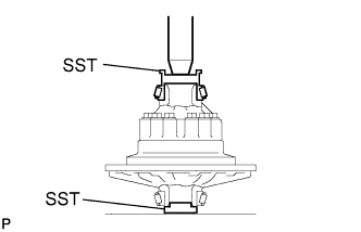
Using SST and a press, install the rear bearing onto the drive pinion.
- SST
- 09506-35010
-
-
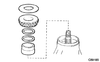
ADJUST DIFFERENTIAL DRIVE PINION PRELOAD
-
Install the drive pinion, spacer, differential oil storage ring, 2 shims, front bearing and oil slinger.
Tech Tips
-
When replace the drive pinion bearing, install the thickest shim A and B.
-
Assemble and install the oil seal after adjusting the total preload.
-
-
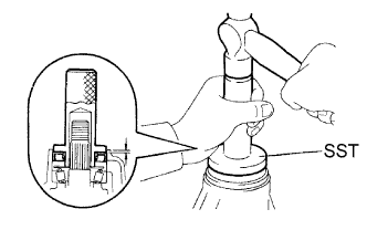
Using SST, install the drive pinion companion flange.
- SST
- 09950-30012 ( 09951-03010, 09953-03010, 09954-03010, 09955-03030, 09956-03040 )
- 09330-00021 ( 09330-00030 )
- 09330-00021
-
Coat the threads of the nut with hypoid oil LSD.
-
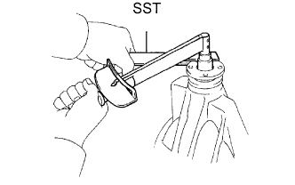
Using SST to hold the flange, torque the nut.
- SST
- 09330-00021
- Torque:
- 275 to 333 N*m { 2804 to 3396 kgf*cm, 203 to 246 ft.*lbf }
Note
As there is no spacer, torque a little at a time, being careful not to overtighten it.
-
Using a dial indicator, measure and note the drive pinion axial play.
-
Calculate the value "T".
T = 4.89 mm (0.1925 in.) - (drive pinion axal play)
Select shims A and B so that the sum of the 2 shims is closest to value "T"
Shim A thickness mm (in.)
at intervals of 0.1 (0.0039)
Shim B thickness mm (in.)
at intervals of 0.01 (0.0004)
1.90 (0.0748) 2.50 (0.0984) 1.80 (0.0709) 1.85 (0.0728) 2.00 (0.0787) 2.60 (0.1024) 1.81 (0.0713) 1.86 (0.0732) 2.10 (0.0827) 2.70 (0.1063) 1.82 (0.0717) 1.87 (0.0736) 2.20 (0.0866) 2.80 (0.1102) 1.83 (0.0720) 1.88 (0.0740) 2.30 (0.0906) 2.90 (0.1142) 1.84 (0.0724) 1.89 (0.0744) 2.40 (0.0945) 3.00 (0.1181) - -
Using a torque wrench, measure the preload.
Preload (at starting):
New bearing 2.00 to 5.39 N*m (20 to 55 kgf*cm, 18 to 48 in.*lbf) Reused bearing 1.00 to 2.76 N*m (10 to 28 kgf*cm, 8.9 to 24 in.*lbf)
-
-
INSTALL DIFFERENTIAL CASE ASSEMBLY
-
Place the 2 bearing outer races on their respective bearings.
Tech Tips
Make sure the right and left races are not interchanged.
-
Install the 2 adjusting nuts on the carrier, making sure the nuts are threaded properly.
-
-
INSPECT AND ADJUST BACKLASH DIFFERENTIAL RING GEAR AND DIFFERENTIAL DRIVE PINION
-
Text in Illustration *a Matchmark Align the matchmarks on the cap and carrier.
-
Install the right and left bearing caps with the 4 bolts.
- Torque:
- 205 N*m { 2091 kgf*cm, 151 ft.*lbf }
-
Tech Tips
-
If the bearing cap does not fit tightly on the carrier, the adjusting nuts are not threaded properly.
-
Reinstall the adjusting nuts if necessary.
-
-
Torque the 4 bearing cap bolts to the specified torque, then loosen them to the point where the adjusting nuts can be turned by SST.
- SST
- 09504-00011
-
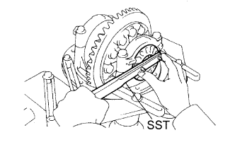
Using the SST, torque the adjusting nut on the ring gear side until the ring has a backlash of about 0.2 mm (0.008 in.).
- SST
- 09504-00011
-
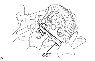
While turning the ring gear, use SST to fully tighten the adjusting nut on the drive pinion side. After the bearings as settled, loosen the adjusting nut on the drive pinion side.
-
Using SST, torque the adjusting nut 1 to 1.5 notches from the 0 preload position.
- SST
- 09504-00011
-
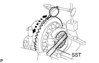
Using a dial indicator, adjust the ring gear backlash until it is within the specification.
Standard backlash 0.15 to 0.20 mm (0.0059 to 0.0079 in.) Tech Tips
-
The backlash is adjusted by turning the left and right adjusting nuts an equal amount. For example, loosen the nut on the right side one notch and loosen the nut on the left side one notch.
-
Perform the measurement at 3 or more positions around the circumference of the ring gear.
-
-
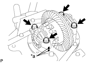
Text in Illustration *a Matchmark Torque the bearing cap bolts.
- Torque:
- 196 N*m { 1997 kgf*cm, 145 ft.*lbf }
-
-
INSPECT TOTAL PRELOAD
-
Using a torque wrench, measure the drive pinion preload.
Total Preload (at starting) Drive pinion preload plus 0.2 to 0.39 N*m (2.0 to 3.0 kgf*cm, 1.8 to 3.5 in.*lbf)
-
-
INSPECT TOOTH CONTACT BETWEEN RING GEAR AND DRIVE PINION
-
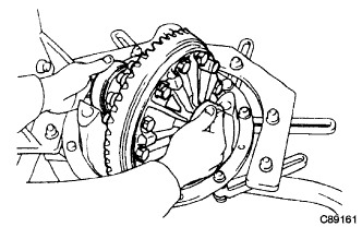
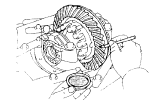
Coat 3 or 4 teeth at 3 different positions on the ring gear with red lead primer.
-
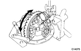
Hold the companion flange firmly in place and rotate the ring gear in both directions.
-
Inspect the tooth contact pattern.
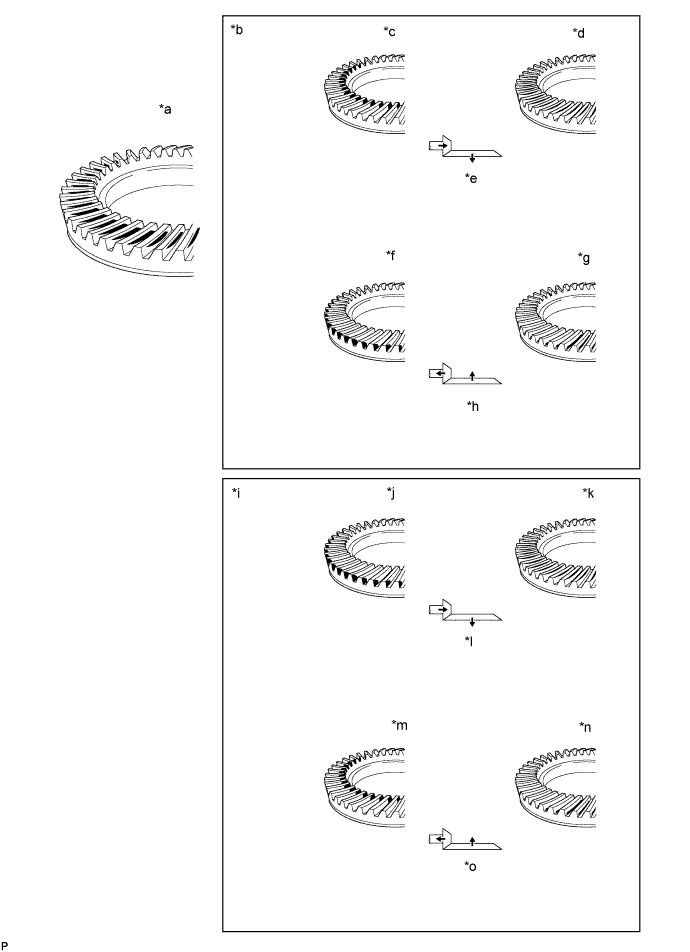
Text in Illustration *a Proper Contact *b Driver Side *c Toe Contact *d Face Contact *e Select an adjusting washer that will bring the drive pinion closer to the ring gear. *f Heel Contact *g Flank Contact *h Select an adjusting washer that will shift the drive pinion away from the ring gear. *i Coast Side *j Heel Contact *k Flank Contact *l Select an adjusting washer that will bring the drive pinion closer to the ring gear. *m Toe Contact *n Face Contact *o Select an adjusting washer that will shift the drive pinion away from the ring gear. - -
-
Text in Illustration *1 Plate Washer If the teeth are not contacting properly, use the following chart to select a proper washer.
Standard plate washer thickness Thickness mm (in.) Thickness mm (in.) 1.05 (0.0413) 1.325 (0.0522) 1.075 (0.0423) 1.35 (0.0531) 1.10 (0.0433) 1.375 (0.0541) 1.125 (0.0443) 1.40 (0.0551) 1.15 (0.0453) 1.425 (0.0561) 1.175 (0.0463) 1.45 (0.0571) 1.20 (0.0472) 1.475 (0.0581) 1.225 (0.0482) 1.50 (0.0591) 1.25 (0.0492) 1.525 (0.0600) 1.275 (0.0502) 1.55 (0.0610) 1.30 (0.0512) -
-
-
-
INSTALL REAR DIFFERENTIAL CARRIER OIL SEAL
-
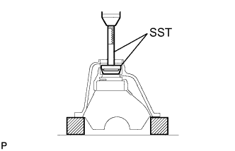
Using SST and a hammer, install a new rear differential carrier oil seal.
- SST
- 09223-78010
Standard oil seal depth 0.45 mm (0.0177 in.) -
Apply MP grease to a new oil seal.
-
-
INSTALL REAR DRIVE PINION COMPANION FLANGE SUB-ASSEMBLY
-
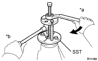
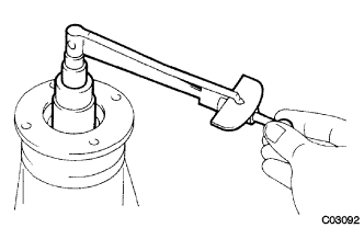
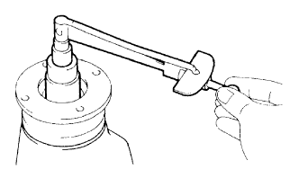
Text in Illustration *a Turn *b Hold Using SST, install the companion flange on the drive pinion.
- SST
- 09950-30012 ( 09951-03010, 09953-03010, 09954-03010, 09955-03030, 09956-03040 )
Note
Before using SST (center bolt), apply hypoid gear oil to its threads and tip.
-
Coat the threads of a new nut with hypoid gear oil LSD.
-
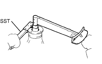
Using SST to hold the flange, torque the nut.
- SST
- 09330-00021 ( 09330-00030 )
- Torque:
- 275 to 333 N*m { 2804 to 3,770 kgf*cm, 203 to 246 ft.*lbf, or less }
-
-
INSPECT DRIVE PINION PRELOAD
-
Using a torque wrench, measure the preload of the backlash between the drive pinion and ring gear.
Standard drive pinion preload (at start of torque) Bearing Preload New bearing 2.00 to 5.39 N*m (20 to 55 kgf*cm, 18 to 48 in.*lbf) Reused bearing 1.00 to 2.76 N*m (10 to 28 kgf*cm, 8.9 to 24 in.*lbf)
-
If the preload is greater than the maximum, replace the bearing spacer.
-
If the preload is less than the minimum, retighten the nut with 13 N*m (130 kgf*cm, 9 ft.*lbf) of torque at a time until the specified preload is reached.
-
-
-
INSPECT TOTAL PRELOAD
-
Using a torque wrench, measure the preload.
Total Preload (at starting) Drive pinion preload plus 0.2 to 0.39 N*m (2.0 to 4.0 kgf*cm, 1.8 to 3.5 in.*lbf)
-
-
INSPECT DIFFERENTIAL RING GEAR BACKLASH
-
INSPECT RUNOUT OF REAR DRIVE PINION COMPANION FLANGE SUB-ASSEMBLY
-
STAKE DRIVE PINION NUT
-
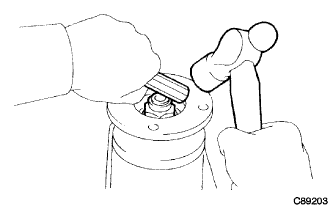
Using a chisel and a hammer, stake the drive pinion nut.
-
-
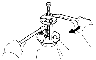
INSTALL REAR DIFFERENTIAL BEARING ADJUSTING NUT LOCK
-
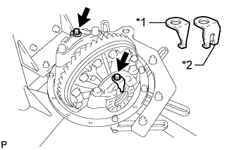
Text in Illustration *1 No. 1 Rear Differential Bearing Adjust Lock *2 No. 2 Rear Differential Bearing Adjust Lock Install 2 new rear differential bearing adjust lock on the bearing caps.
- Torque:
- 13 N*m { 133 kgf*cm, 10 ft.*lbf }
-
After tightening bolts, bend the nut locks.
-