DIFFERENTIAL CARRIER ASSEMBLY (for 4 Pinion Gear Type) DISASSEMBLY

-
FIX REAR DIFFERENTIAL CARRIER ASSEMBLY
-
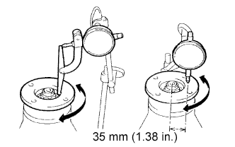
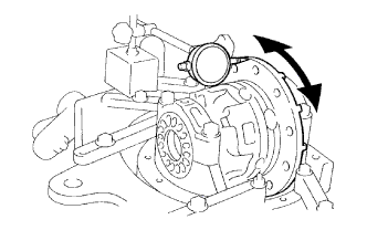
INSPECT RUNOUT OF REAR DRIVE PINION COMPANION FLANGE SUB-ASSEMBLY REAR
-
Using a dial indicator, measure the runout of the companion flange vertically and laterally.
Maximum runout Runout Maximum Vertical runout 0.10 mm (0.0039 in.) Lateral runout 0.15 mm (0.0056 in.) or less
-
If the runout is greater than the maximum, replace the companion flange.
-
-
-
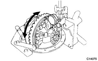
INSPECT RUNOUT OF DIFFERENTIAL RING GEAR
-
Using a dial indicator, measure the runout of the ring gear.
Maximum runout 0.01 mm (0.00039 in.)
-
If the runout is greater than the maximum, replace the ring gear with a new one.
-
-
-
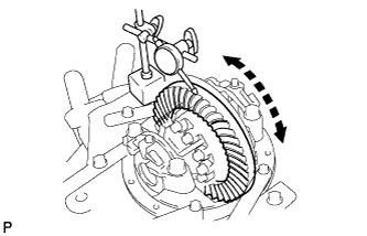
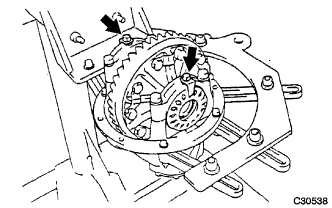
INSPECT DIFFERENTIAL RING GEAR BACKLASH
-
Using a dial indicator, measure the backlash of the ring gear.
Standard backlash 0.15 to 0.20 mm (0.0059 to 0.0079 in.)
-
If the backlash is not within the specification, adjust the side bearing preload or repair as necessary.
Tech Tips
Perform the measurements at 3 or more positions around the side bearing preload.
-
-
-
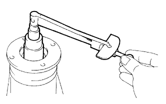
INSPECT DIFFERENTIAL DRIVE PINION PRELOAD
-
Using a torque wrench, measure the preload of backlash between the drive pinion and ring gear.
Preload (at starting) 1.00 to 2.76 N*m (10 to 28 kgf*cm, 8.9 to 24 in.*lbf)
-
-
INSPECT TOTAL PRELOAD
-
Using a torque wrench, measure the total preload.
Total preload (at starting) Drive pinion preload plus 0.20 to 0.39 N*m (2.0 to 3.0 kgf*cm, 1.8 to 3.5 in.*lbf)
-
-
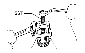
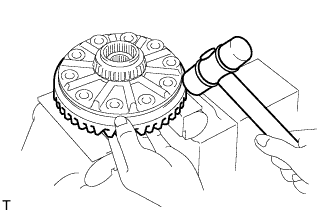
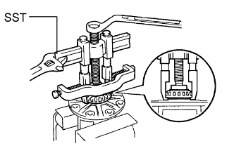
REMOVE REAR DRIVE PINION NUT
-
Using a chisel and a hammer, unstake the staked part of the nut.
-
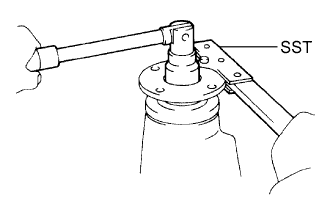
Using SST to hold the flange, remove the nut and washer.
- SST
- 09330-00021
-
-
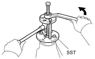
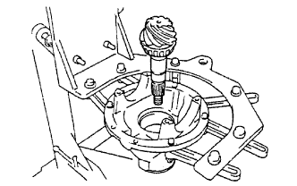
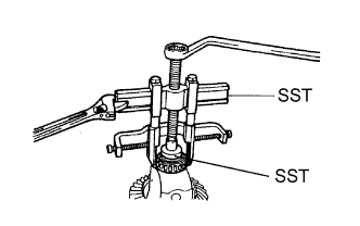
REMOVE REAR DRIVE PINION COMPANION FLANGE SUB-ASSEMBLY
-
Using SST, remove the companion flange.
- SST
- 09950-30012 ( 09951-03010, 09953-03010, 09954-03010, 09955-03030, 09956-03040 )
-
-
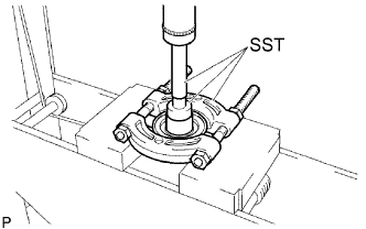
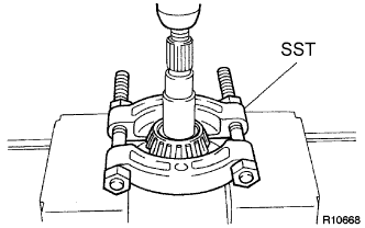
REMOVE REAR DIFFERENTIAL DUST DEFLECTOR
-
Using SST and a press, remove the dust deflector.
- SST
- 09950-60010
- 09950-70010 ( 09951-07150 )
- 09950-00020 ( 09951-00480 )
-
-
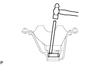
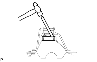
REMOVE REAR DIFFERENTIAL CARRIER OIL SEAL
-
Using SST, remove the oil seal from the differential carrier.
- SST
- 09308-10010
-
-
REMOVE REAR DIFFERENTIAL DRIVE PINION OIL SLINGER
-
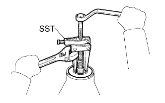
REMOVE REAR DRIVE PINION FRONT TAPERED ROLLER BEARING
-
Using SST, remove the rear drive pinion tapered roller bearing from the drive pinion.
- SST
- 09556-22010
-
Remove the rear differential drive pinion spacer adjust shim FR and differential oil storage ring.
-
-
REMOVE REAR DIFFERENTIAL BEARING ADJUSTING NUT LOCK
-
Remove the 2 bolts and rear differential bearing adjust locks.
-
-
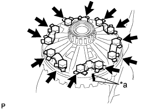
REMOVE DIFFERENTIAL CASE ASSEMBLY
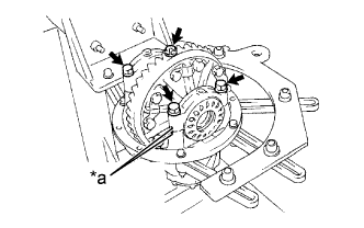
Text in Illustration *a Matchmark
-
Place matchmarks on the bearing cap and differential carrier.
-
Remove the 4 bolts and 2 differential bearing caps.
-
Remove the 2 rear differential bearing adjusting nuts.
-
Remove the rear differential case assembly and 2 bearring outer races from the differential carrier.
Tech Tips
Tag the 2 bearing outer races to show the location for reassembling.
-
-
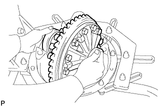
REMOVE DIFFERENTIAL DRIVE PINION
-
Remove the differential drive pinion from the differential carrier.
-
-
REMOVE REAR DRIVE PINION REAR TAPERED ROLLER BEARING
-
Using SST and a press, remove the rear drive pinion tapered roller bearing RR from the drive pinion.
- SST
- 09950-00020
Tech Tips
If the drive pinion or ring gear are damaged, replace them as a set.
-
-
REMOVE REAR DRIVE PINION FRONT TAPERED ROLLER BEARING
-
Using SST, remove the roller bearing (outer) from the carrier.
- SST
- 09308-00010
-
Using a brass bar and a hammer, tap out the oil storage ring from the carrier.
Tech Tips
If the bearing is damaged during removal, replace it.
-
-
REMOVE REAR DRIVE PINION REAR TAPERED ROLLER BEARING
-
Using a brass bar and a hammer, remove the rear tapered roller bearing (outer race) from the carrier.
-
-
REMOVE DIFFERENTIAL RING GEAR
Text in Illustration *a Matchmark
-
Place matchmarks on the ring gear and differential case.
-
Using a screwdriver and a hammer, pry out the lock plates.
-
Remove the 12 ring gear set bolts and 6 rear differential ring gear plate.
-
Using a plastic hammer, tap on the ring gear to separate it from the differential case.
-
-
INSPECT DIFFERENTIAL CASE ASSEMBLY RUNOUT
-
Install the rear differential case bearing to the differential case.
-
Install the differential case to the differential carrier.
-
Install the rear differential cap and 4 bolts to the differential carrier.
- Torque:
- 196 N*m { 2000 kgf*cm, 146 ft.*lbf }
-
Inspect the differential case runout.
Maximum runout 0.05 mm (0.002 in.) -
Remove the differential case.
-
Remove the rear differential case bearing.
-
-
REMOVE REAR DIFFERENTIAL CASE BEARING
-
Using SST, remove the rear differential case bearing (LH) from the differential case.
- SST
- 09950-40011 ( 09951-04020, 09952-04010, 09953-04030, 09954-04010, 09955-04061, 09957-04010, 09958-04011 )
- 09950-60010 ( 09951-00480 )
-
Using SST, remove the rear differential case bearing (RH) from the differential case.
- SST
- 09950-40011 ( 09951-04020, 09952-04010, 09953-04030, 09954-04010, 09955-04061, 09957-04010, 09958-04011 )
- 09950-60010 ( 09951-00480 )
-
-
DISASSEMBLE DIFFERENTIAL CASE
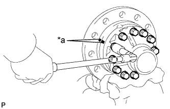
Text in Illustration *a Matchmark
-
Place matchmarks on the LH and RH cases.
-
Remove the 12 bolts.
-
Using a plastic hammer, separate the LH and RH case.
-
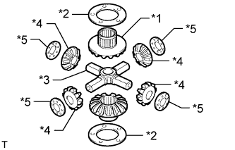
Text in Illustration *1 Differential side gear *2 Rear differential side gear thrust washer *3 Rear differential spider *4 Differential pinion *5 Rear differential pinion thrust washer Remove these parts from the differential case.
-
-
INSPECT DIFFERENTIAL PINION AND SIDE GEAR
-
Check that no damage is identified on the differential pinion and differential side gear.
-
If the differential pinion and/or differential side gear is damaged, replace the differential.
-
-
-
INSPECT DIFFERENTIAL CASE
-
Check that no damaged is differential case.
-
If the differential case is damaged, replace the differential case.
-
-