MANUAL TRANSMISSION ASSEMBLY INSTALLATION

-
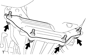
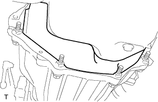
INSTALL REAR ENGINE MOUNTING INSULATOR ASSEMBLY
-
Install the rear engine mounting insulator with the 4 bolts.
- Torque:
- 38 N*m { 387 kgf*cm, 28 ft.*lbf }
-
-
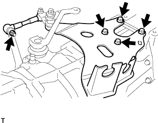
INSTALL FLOOR SHIFT CONTROL ROD SUPPORT SUB-ASSEMBLY
-
Install the floor shift control rod support with the 4 bolts.
- Torque:
- 31 N*m { 316 kgf*cm, 23 ft.*lbf }
-
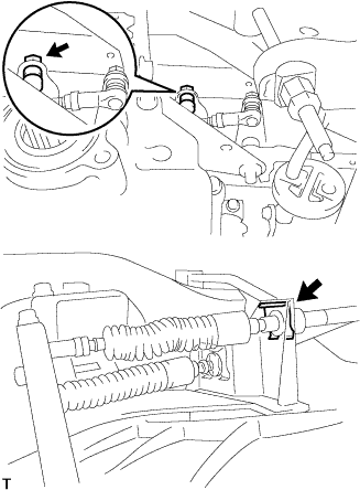
Connect the shift cable link with the nut.
- Torque:
- 12 N*m { 122 kgf*cm, 8.9 ft.*lbf }
-
-
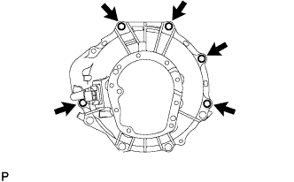
INSTALL MANUAL TRANSMISSION ASSEMBLY
-
Install the manual transmission with the 5 bolts.
- Torque:
- 72 N*m { 729 kgf*cm, 53 ft.*lbf }
-
-
INSTALL NO. 2 REAR END PLATE
-
Install the No. 2 rear end plate with the 4 bolts.
- Torque:
- 73 N*m { 744 kgf*cm, 54 ft.*lbf }
-
-
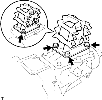
INSTALL NO. 4 CYLINDER BLOCK INSULATOR
-
Install the No. 4 cylinder block insulator.
-
-
CONNECT REAR ENGINE MOUNTING INSULATOR ASSEMBLY
-
Install the rear engine mounting insulator onto the rear engine mounting bracket with the bolt and nut.
- Torque:
- 98 N*m { 999 kgf*cm, 72 ft.*lbf }
-
-
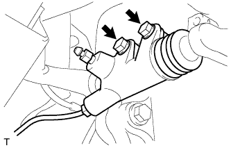
INSTALL CLUTCH RELEASE CYLINDER ASSEMBLY
-
Install the clutch release cylinder with the 2 bolts.
- Torque:
- 12 N*m { 119 kgf*cm, 8.6 ft.*lbf }
-
-
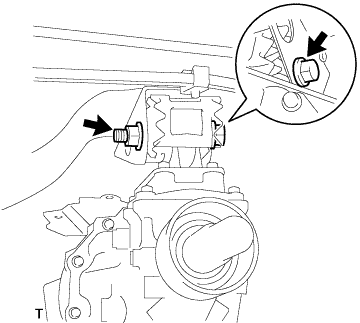
INSTALL STARTER ASSEMBLY
-
Install the starter with the bolt and nut.
- Torque:
- 68 N*m { 693 kgf*cm, 50 ft.*lbf }
-
Install the wire harness with the nut.
- Torque:
- 9.8 N*m { 100 kgf*cm, 7 ft.*lbf }
-
Connect the connector.
-
-
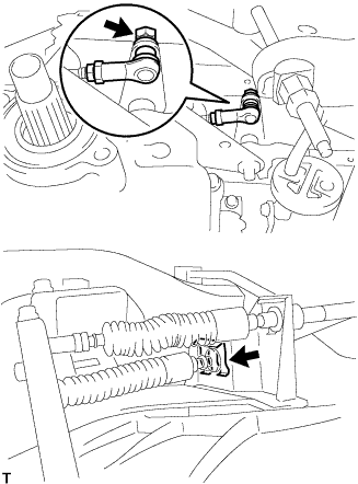
CONNECT TRANSMISSION CONTROL SELECT CABLE
-
Connect the select cable with a new clip and nut.
- Torque:
- 12 N*m { 122 kgf*cm, 8.9 ft.*lbf }
-
-
CONNECT TRANSMISSION CONTROL SHIFT CABLE
-
Connect the shift cable with a new clip and nut.
- Torque:
- 12 N*m { 122 kgf*cm, 8.9 ft.*lbf }
-
-
CONNECT WIRE HARNESS
-
Connect the speed sensor connector.
-
Connect the back-up light switch connector.
-
-
INSTALL PROPELLER SHAFT ASSEMBLY
-
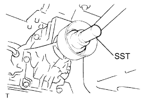
Remove SST from the extension housing.
-
Install the propeller shaft assembly in the extension housing.
-
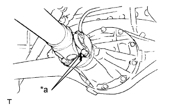
Text in Illustration *a Matchmark Align the matchmarks on the propeller shaft flange and differential flange.
-
Install the 4 nuts, 4 bolts and 4 washers.
- Torque:
- 74 N*m { 749 kgf*cm, 54 ft.*lbf }
-
-
INSTALL FRONT EXHAUST PIPE ASSEMBLY
-
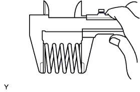
Inspect the compression spring.
-
Using vernier calipers, measure the free length of the compression spring.
Minimum length 40.5 mm (1.594 in.) If the free length is less than the minimum, replace the compression spring.
-
-
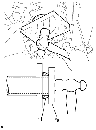
Text in Illustration *1 New Gasket *a Wooden Block Fully insert a new gasket into the turbine outlet elbow by hand.
Note
-
Install the gasket in the correct direction.
-
Do not damage the outer surface of the gasket.
-
Do not reuse the gasket.
-
Do not push in the gasket with the front exhaust pipe when connecting it.
-
-
Using a wooden block, uniformly strike the gasket so that the gasket and the turbine outlet elbow are properly fitted.
-
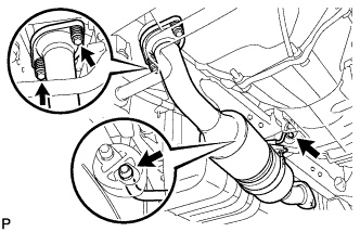
Install the 2 hungers and the front exhaust pipe.
-
Install the 2 bolts and the 2 compression springs.
- Torque:
- 43 N*m { 438 kgf*cm, 32 ft.*lbf }
-
-
ADD MANUAL TRANSMISSION OIL
-
INSPECT AND ADJUST MANUAL TRANSMISSION OIL
-
CONNECT CABLE TO NEGATIVE BATTERY TERMINAL
- Torque:
- 3.9 N*m { 39 kgf*cm, 34 in.*lbf }
-
INSPECT FOR OIL LEAK
-
INSPECT FOR EXHAUST GAS LEAK