MANUAL TRANSMISSION ASSEMBLY REMOVAL

-
DISCONNECT CABLE FROM NEGATIVE BATTERY TERMINAL
-
DRAIN MANUAL TRANSMISSION OIL
-
Remove the drain plug and gasket and then drain the manual transmission oil.
-
Install a new gasket and drain plug.
- Torque:
- 37 N*m { 377 kgf*cm, 27 ft.*lbf }
-
-
REMOVE FRONT EXHAUST PIPE ASSEMBLY
-
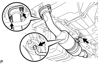
Remove the 2 bolts and the 2 compression springs.
-
Remove the 2 hangers and the front exhaust pipe.
-
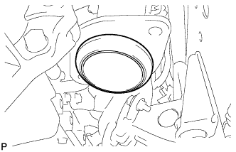
Remove the gasket.
-
-
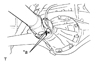
REMOVE PROPELLER SHAFT ASSEMBLY
-
Place matchmarks on the propeller shaft flange and differential flange.
Text in Illustration *a Matchmark -
Remove the 4 nuts, 4 bolts and 4 washers.
-
Remove the propeller shaft assembly.
-
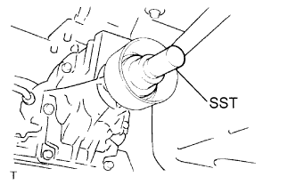
Insert SST into the extension housing to prevent oil leakage.
Note
Do not damage the oil seal.
-
Use the following SST for the R351 manual transmission.
- SST
- 09325-40010
-
Use the following SST for the G54 manual transmission.
- SST
- 09325-20010
-
-
-
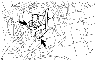
DISCONNECT WIRE HARNESS
-
Disconnect the back-up light switch connector.
-
Disconnect the speed sensor connector.
-
-
DISCONNECT TRANSMISSION CONTROL SHIFT CABLE
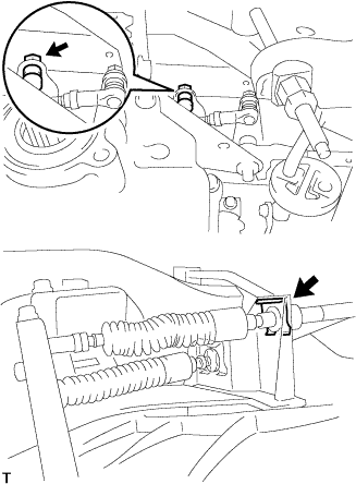
-
Remove the nut.
-
Remove the clip and disconnect the shift cable.
-
-
DISCONNECT TRANSMISSION CONTROL SELECT CABLE
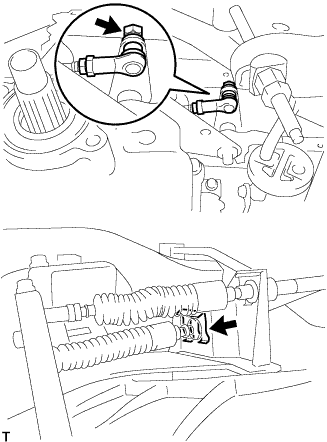
-
Remove the nut.
-
Remove the clip and disconnect the select cable.
-
-
REMOVE STARTER ASSEMBLY
-
Disconnect the connector.
-
Open the terminal cap.
-
Remove the nut and disconnect the wire harness.
-
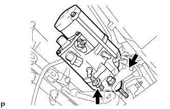
Remove the bolt and nut and remove the starter.
-
-
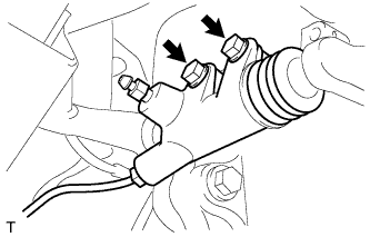
SEPARATE CLUTCH RELEASE CYLINDER ASSEMBLY
-
Remove the 2 bolts and separate the clutch release cylinder.
-
-
SUPPORT MANUAL TRANSMISSION ASSEMBLY
-
Support the manual transmission with a transmission jack.
-
-
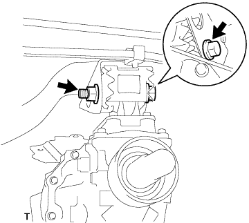
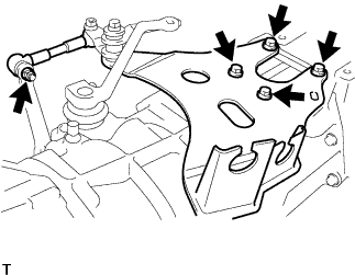
SEPARATE REAR ENGINE MOUNTING INSULATOR ASSEMBLY
-
Remove the bolt and nut and separate the rear engine mounting insulator from the rear engine mounting bracket.
-
-
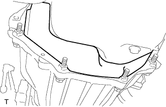
REMOVE NO. 4 CYLINDER BLOCK INSULATOR
-
Remove the No. 4 cylinder block insulator.
-
-
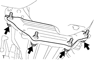
REMOVE NO. 2 REAR END PLATE
-
Remove the 4 bolts and the No. 2 rear end plate.
-
-
REMOVE MANUAL TRANSMISSION ASSEMBLY
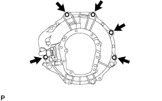
-
Remove the 5 bolts and the manual transmission.
-
-
REMOVE FLOOR SHIFT CONTROL ROD SUPPORT SUB-ASSEMBLY
-
Remove the nut and disconnect the shift cable link.
-
Remove the 4 bolts and the floor shift control rod support.
-
-
REMOVE REAR ENGINE MOUNTING INSULATOR ASSEMBLY
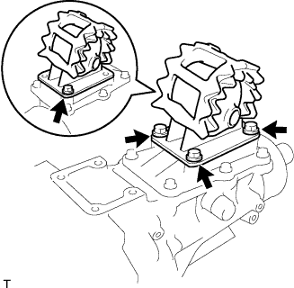
-
Remove the 4 bolts and the rear engine mounting insulator.
-