OUTPUT SHAFT DISASSEMBLY

-
INSPECT 5TH GEAR THRUST CLEARANCE
-
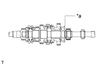
Text in Illustration *a 5th gear thrust clearance Using a feeler gauge, measure the 5th gear thrust clearance.
Standard clearance 0.1 to 0.3 mm (0.0039 to 0.0118 in.)
-
-
INSPECT 1ST GEAR THRUST CLEARANCE
-
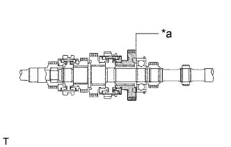
Text in Illustration *a 1st gear thrust clearance Using a feeler gauge, measure the 1st gear thrust clearance.
Standard clearance 0.1 to 0.25 mm (0.0039 to 0.0098 in.)
-
-
INSPECT 2ND GEAR THRUST CLEARANCE
-
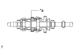
Text in Illustration *a 2nd gear thrust clearance Using a feeler gauge, measure the 2nd gear thrust clearance.
Standard clearance 0.1 to 0.25 mm (0.0039 to 0.0098 in.)
-
-
INSPECT 3RD GEAR THRUST CLEARANCE
-
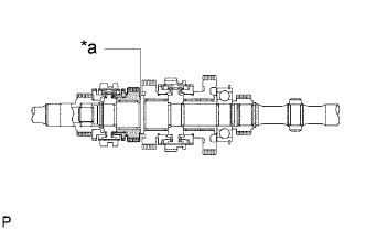
Text in Illustration *a 3rd gear thrust clearance Using a feeler gauge, measure the 3rd gear thrust clearance.
Standard clearance 0.1 to 0.25 mm (0.0039 to 0.0098 in.)
-
-
INSPECT 1ST GEAR RADIAL CLEARANCE
-
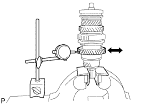
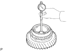
Using a dial indicator, measure the 1st gear radial clearance between the gear and shaft.
Standard clearance 0.009 to 0.056 mm (0.0004 to 0.00220 in.) If the clearance exceeds the maximum, replace the 1st gear needle roller bearing.
-
-
INSPECT 2ND GEAR RADIAL CLEARANCE
-
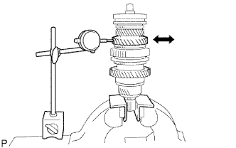
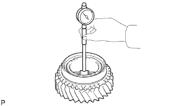
Using a dial indicator, measure the 2nd gear radial clearance between the gear and shaft.
Standard clearance 0.008 to 0.034 mm (0.0003 to 0.00134 in.) If the clearance exceeds the maximum, replace the 1st gear needle roller bearing.
-
-
INSPECT 3RD GEAR RADIAL CLEARANCE
-
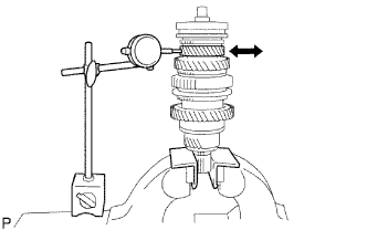
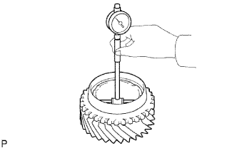
Using a dial indicator, measure the 3rd gear radial clearance between the gear and shaft.
Standard clearance 0.008 to 0.034 mm (0.0003 to 0.00134 in.) If the clearance exceeds the maximum, replace the 3rd gear needle roller bearing.
-
-
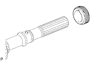
REMOVE SPEEDOMETER DRIVE (MTM) GEAR
-
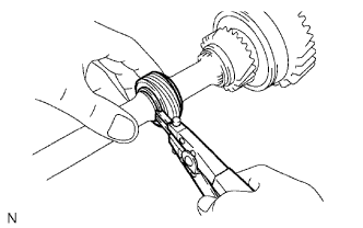
Using a snap ring expander, remove the 2 speedometer drive gear rings from the output shaft.
-
Remove the speedometer drive gear from the output shaft.
-
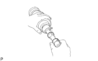
Remove the inner race lock ball from the output shaft.
-
-
REMOVE 1ST GEAR
-
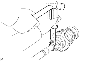
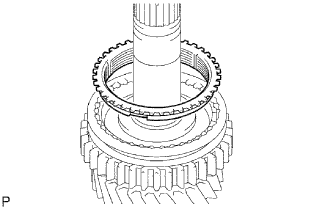
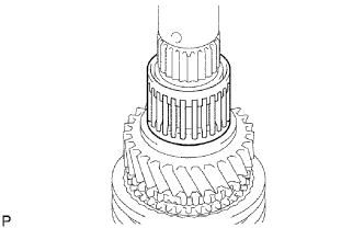
Using 2 screwdrivers and a hammer, remove the output shaft bearing shaft snap ring from the output shaft.
-
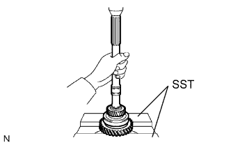
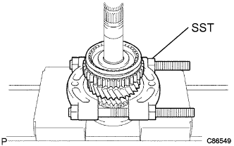
Using SST and a press, remove the 5th gear, output shaft bearing RR, 1st gear, 1st gear needle roller bearing and the 1st gear bearing inner race from the output shaft.
- SST
- 09527-10011
-
-
REMOVE SYNCHRONIZER RING NO.2 (FOR FIRST SYNCHRONIZER RING)
-
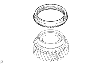
Remove the synchronizer ring No. 2 (for first synchronizer ring) from the transmission clutch hub No. 1.
-
-
REMOVE 1ST GEAR BEARING INNER RACE LOCK KEY OR BALL
-
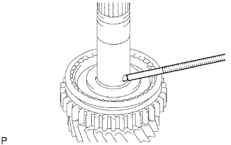
Using a magnetic finger, remove the 1st gear bearing inner race lock key from the output shaft.
-
-
REMOVE 2ND GEAR
-
Using SST and a press, remove the transmission clutch hub No. 1 assembly and the 2nd gear from the output shaft.
- SST
- 09950-00020
-
-
REMOVE SYNCHRONIZER RING NO.2 (FOR SECOND SYNCHRONIZER RING)
-
Remove the synchronizer ring No. 2 (for second synchronizer ring) from the 2nd gear.
-
-
REMOVE 2ND GEAR NEEDLE ROLLER BEARING
-
Remove the 2nd gear needle roller bearing from the output shaft.
-
-
REMOVE TRANSMISSION CLUTCH HUB NO.1
-
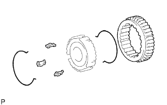
Remove the 2 synchromesh shifting key springs No. 1.
-
Remove the reverse gear and the 3 synchromesh shifting keys No. 1 from the transmission clutch hub No. 1.
-
-
REMOVE 3RD GEAR
-
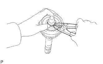
Using a snap ring expander, remove the clutch hub shaft snap ring from the output shaft.
-
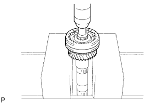
Using a press, remove the clutch hub No. 2 assembly and the 3rd gear.
-
-
REMOVE SYNCHRONIZER RING NO.1
-
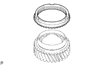
Remove the synchronizer ring No. 1 from the 3rd gear.
-
-
REMOVE 3RD GEAR NEEDLE ROLLER BEARING
-
Remove the 3rd gear needle roller bearing from the output shaft.
-
-
REMOVE TRANSMISSION CLUTCH HUB NO.2
-
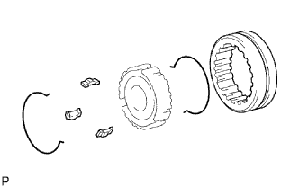
Remove the 2 synchromesh shifting key springs No. 2.
-
Remove the transmission hub sleeve No. 2 and the 3 synchromesh shifting keys No. 2 from the transmission clutch hub No. 2.
-
-
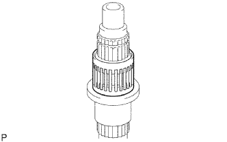
INSPECT OUTPUT SHAFT
-
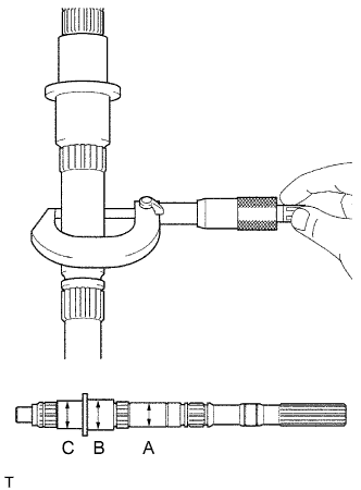
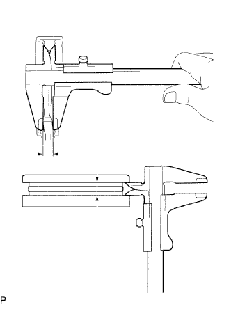
Using a micrometer, measure the outer diameter of the output shaft journal surface.
Standard outer diameter Part A 30.384 to 30.400 mm (1.1962 to 1.1968 in.) Part B 37.984 to 38.000 mm (1.4954 to 1.4960 in.) Part C 34.984 to 35.000 mm (1.3773 to 1.3780 in.) Minimum outer diameter Part A 30.384 mm (1.1962 in.) Part B 37.984 mm (1.4954 in.) Part C 34.984 mm (1.3773 in.) If the outer diameter is less than the minimum, replace the output shaft.
-
Using a micrometer, measure the output shaft flange thickness.
Standard thickness 4.80 to 5.20 mm (0.189 to 0.204 in.) Minimum thickness 4.80 mm (0.189 in.)
-
If the thickness is less than the minimum, replace the output shaft.
-
-
-
INSPECT 1ST GEAR BEARING INNER RACE
-
Using a micrometer, measure the 1st gear bearing inner race thickness.
Standard thickness 4.00 to 4.20 mm (0.1575 to 0.1654 in.) Minimum thickness 4.00 mm (0.1575 in.) If the thickness is less than the minimum, replace the 1st gear bearing inner race.
-
Using a micrometer, measure the outer diameter of the 1st gear bearing inner race.
Standard thickness 38.985 to 39.000 mm (1.5348 to 1.5354 in.) Minimum thickness 38.985 (1.5348 in.) If the outer diameter is less than the minimum, replace the 1st gear bearing inner race.
-
-
INSPECT SYNCHRONIZER RING NO.2 (FOR FIRST SYNCHRONIZER RING)
-
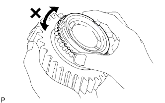
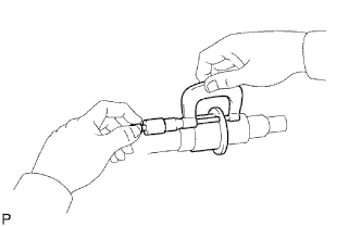
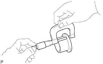
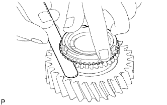
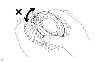
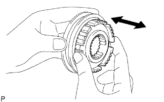
Coat the 1st gear cone with gear oil. Check the braking effect of the synchronizer ring No. 2 (for first synchronizer ring). Turn the synchronizer ring No. 2 (for first synchronizer ring) in one direction while pushing it to the 1st gear cone. Check that the ring locks.
If the braking effect is insufficient, apply a small amount of the fine lapping compound between the synchronizer ring No. 2 (for first synchronizer ring) and the 1st gear cone. Lightly rub the synchronizer ring No. 2 (for first synchronizer ring) and the 1st gear cone together.
Note
Ensure the fine lapping compound is completely washed off after rubbing.
-
Check again the braking effect of the synchronizer ring No. 2 (for first synchronizer ring).
-
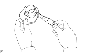
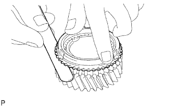
Using a feeler gauge, measure the clearance between the synchronizer ring No. 2 (for first synchronizer ring) back and the 1st gear spline end.
Standard clearance 1.0 to 2.0 mm (0.0394 to 0.0787 in.) If the clearance is less than the minimum, replace the synchronizer ring No. 2 (for first synchronizer ring) and apply a small amount of the fine lapping compound on the 1st gear cone.
Note
Ensure the fine lapping compound is completely washed off after rubbing.
-
-
INSPECT SYNCHRONIZER RING NO.2 (FOR SECOND SYNCHRONIZER RING)
-
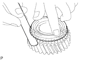
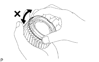
Coat the 2nd gear cone with gear oil. Check the braking effect of the synchronizer ring No. 2 (for second synchronizer ring). Turn the synchronizer ring No. 2 (for second synchronizer ring) in one direction while pushing it to the 2nd gear cone. Check that the ring locks.
If the braking effect is insufficient, apply a small amount of the fine lapping compound between the synchronizer ring No. 2 (for second synchronizer ring) and the 2nd gear cone. Lightly rub the synchronizer ring No. 2 (for second synchronizer ring) and the 2nd gear cone together.
Note
Ensure the fine lapping compound is completely washed off after rubbing.
-
Check again the braking effect of the synchronizer ring No. 2 (for second synchronizer ring).
-
Using a feeler gauge, measure the clearance between the synchronizer ring No. 2 (for second synchronizer ring) back and the 2nd gear spline end.
Standard clearance 1.0 to 2.0 mm (0.0394 to 0.0787 in.) If the clearance is less than the minimum, replace the synchronizer ring No. 2 (for second synchronizer ring) and apply a small amount of the fine lapping compound on the 2nd gear cone.
Note
Ensure the fine lapping compound is completely washed off after rubbing.
-
-
INSPECT SYNCHRONIZER RING NO.1
-
Coat the 3rd gear cone with gear oil. Check the braking effect of the synchronizer ring No. 1. Turn the synchronizer ring No. 1 in one direction while pushing it to the 3rd gear cone. Check that the ring locks.
If the braking effect is insufficient, apply a small amount of the fine lapping compound between the synchronizer ring No. 1 and the 3rd gear cone. Lightly rub the synchronizer ring No. 1 and the 3rd gear cone together.
Note
Ensure the fine lapping compound is completely washed off after rubbing.
-
Check again the braking effect of the synchronizer ring No. 1.
-
Using a feeler gauge, measure the clearance between the synchronizer ring No. 1 back and the 3rd gear spline end.
Standard clearance 1.0 to 2.0 mm (0.0394 to 0.0787 in.)
-
If the clearance is less than the minimum, replace the synchronizer ring No. 1 and apply a small amount of the fine lapping compound on the 3rd gear cone.
Note
Ensure the fine lapping compound is completely washed off after rubbing.
-
-
-
INSPECT REVERSE GEAR
-
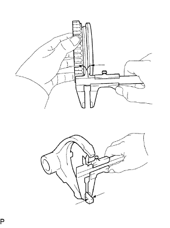
Using a vernier caliper, measure the clearance between the reverse gear and the gear shift fork No. 1.
Standard clearance 0.15 to 0.35 mm (0.0059 to 0.0138 in.) Maximum clearance 0.35 mm (0.0138 in.) If the clearance exceeds the maximum, replace the gear shift fork No. 1 and the reverse gear.
-
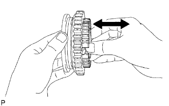
Check that the transmission clutch hub No. 1 and the reverse gear slides smoothly.
-
Check that the spline gear's edges of the reverse gear is not worn down.
-
-
INSPECT TRANSMISSION HUB SLEEVE NO.2
-
Using a vernier caliper, inspect the transmission hub sleeve No. 2 and the gear shift fork No. 2 as shown in the illustration.
Standard clearance 0.26 to 0.84 mm (0.0102 to 0.0331 in.) If the clearance exceeds the standard clearance, replace the transmission hub sleeve No. 2 and the gear shift fork No. 2.
-
Check the sliding condition between the transmission hub sleeve No. 2 and the transmission clutch hub No. 2.
-
Check that the spline gear's edges of the transmission hub sleeve No. 2 is not worn down.
-
-
INSPECT 1ST GEAR
-
Using a cylinder gauge, measure the inside diameter of the 1st gear.
Standard clearance 44.015 to 44.040 mm (1.7329 to 1.7339 in.) Maximum clearance 44.040 mm (1.7339 in.) If the clearance exceeds the maximum, replace the 1st gear.
-
-
INSPECT 2ND GEAR
-
Using a cylinder gauge, measure the inside diameter of the 2nd gear.
Standard clearance 44.015 to 44.040 mm (1.7329 to 1.7339 in.) Maximum clearance 44.040 mm (1.7339 in.) If the clearance exceeds the maximum, replace the 2nd gear.
-
-
INSPECT 3RD GEAR
-
Using a cylinder gauge, measure the inside diameter of the 3rd gear.
Standard clearance 44.015 to 44.040 mm (1.7329 to 1.7339 in.) Maximum clearance 44.040 mm (1.7339 in.) If the clearance exceeds the maximum, replace the 3rd gear.
-