OUTPUT SHAFT REASSEMBLY

-
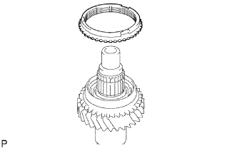
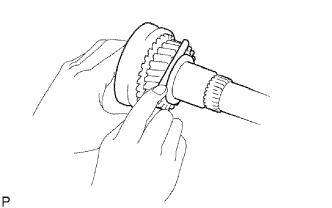
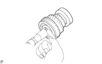
INSTALL TRANSMISSION CLUTCH HUB NO.2
-
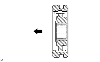
Coat the transmission hub sleeve No. 2 with gear oil, install it to the transmission clutch hub No. 2.
Text in Illustration 
Front Note
Do not set the transmission clutch hub sleeve No. 2 and the transmission clutch hub No. 2 in incorrect orientation.
-
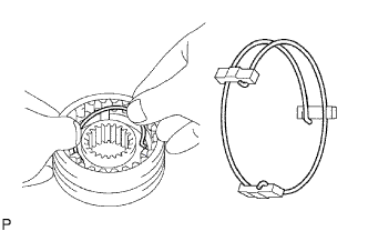
Install the 2 synchromesh shifting key springs No. 2 with the 3 synchromesh shifting keys No. 2 to the transmission clutch hub No. 2.
Tech Tips
Do not set the both openings of the shifting key springs in the same position.
-
-
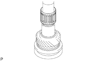
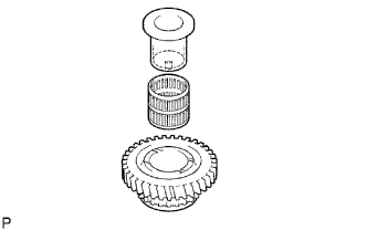
INSTALL 3RD GEAR NEEDLE ROLLER BEARING
-
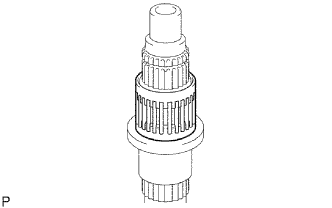
Coat the 3rd gear bearing with gear oil, install it to the output shaft.
-
-
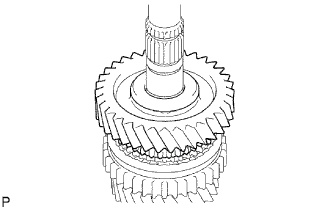
INSTALL 3RD GEAR
-
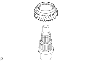
Coat the 3rd gear with gear oil, install it to the output shaft.
-
-
INSTALL SYNCHRONIZER RING NO.1
-
Coat the synchronizer ring No. 1 with gear oil, install it to the 3rd gear.
-
-
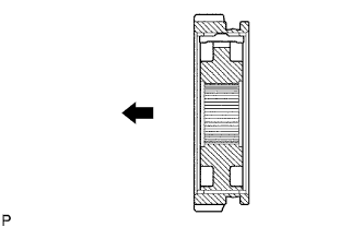
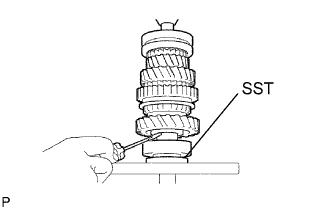
INSTALL TRANSMISSION CLUTCH HUB NO.2
-
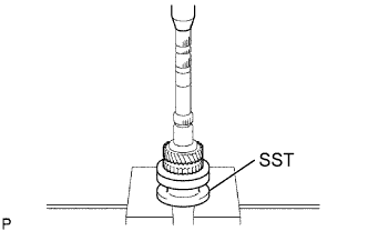
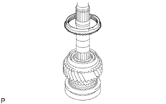
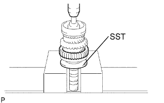
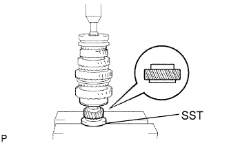
Using SST and a press, install the transmission clutch hub No. 2 to the output shaft.
- SST
- 09316-60011 ( 09316-00021 )
-
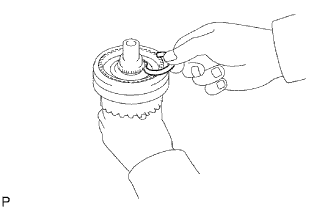
Select a clutch hub shaft snap ring that will allow minimum axial play.
Standard clearance 0.1 mm (0.0039 in.) or less Clutch hub shaft snap ring thickness Mark Thickness C-1 1.75 to 1.80 mm (0.0689 to 0.0709 in.) D 1.80 to 1.85 mm (0.0709 to 0.0728 in.) D-1 1.85 to 1.90 mm (0.0728 to 0.0748 in.) E 1.90 to 1.95 mm (0.0748 to 0.0768 in.) E-1 1.95 to 2.00 mm (0.0768 to 0.0787 in.) F 2.00 to 2.05 mm (0.0787 to 0.0807 in.) F-1 2.05 to 2.10 mm (0.0807 to 0.0827 in.) -
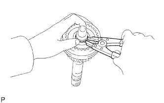
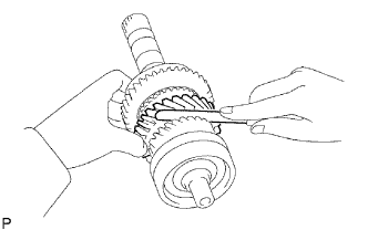
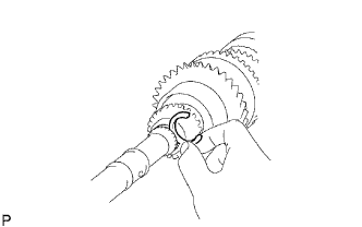
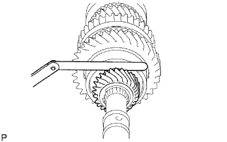
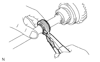
Using a snap ring expander, install the clutch hub shaft snap ring.
-
-
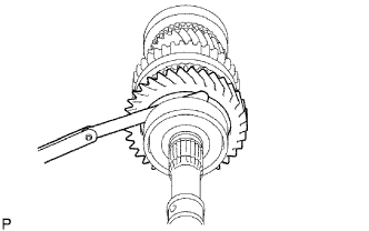
INSPECT 3RD GEAR THRUST CLEARANCE
-
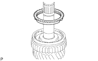
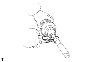
Using a feeler gauge, measure the 3rd gear thrust clearance.
Standard clearance 0.1 to 0.25 mm (0.0039 to 0.0098 in.)
-
-
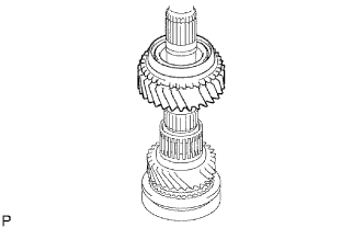
INSTALL TRANSMISSION CLUTCH HUB NO.1
-
Coat the reverse gear with gear oil, install it to the transmission clutch hub No. 1.
Text in Illustration Front Note
Do not set the reverse gear and the transmission clutch hub No. 1 in incorrect orientation.
-
Install the 2 synchromesh shifting key springs No. 1 and the 3 synchromesh shifting keys No. 1.
Tech Tips
Do not set both openings of the shifting key springs in the same position.
-
-
INSTALL 2ND GEAR NEEDLE ROLLER BEARING
-
Coat the 2nd gear needle roller bearing with gear oil, install it to the output shaft.
-
-
INSTALL 2ND GEAR
-
Coat the 2nd gear with gear oil, install it to the output shaft.
-
-
INSTALL SYNCHRONIZER RING NO.2 (FOR SECOND SYNCHRONIZER RING)
-
Coat the synchronizer ring No. 2 (for second synchronizer ring) with gear oil, install it to the 2nd gear.
-
-
INSTALL TRANSMISSION CLUTCH HUB NO.1
-
Using SST and a press, install the transmission clutch hub No. 1 to the output shaft.
- SST
- 09316-60011 ( 09316-00021 )
-
-
INSPECT 2ND GEAR THRUST CLEARANCE
-
Using a feeler gauge, measure the 2nd gear thrust clearance.
Standard clearance 0.1 to 0.25 mm (0.0039 to 0.0098 in.)
-
-
INSTALL SYNCHRONIZER RING NO.2 (FOR FIRST SYNCHRONIZER RING)
-
Coat the synchronizer ring No. 2 (for first synchronizer rig) with gear oil, install it to the transmission clutch hub No. 2.
-
-
INSTALL 1ST GEAR BEARING INNER RACE LOCK KEY OR BALL
-
Coat the 1st gear bearing inner lock key with gear oil, install it to the output shaft.
-
-
INSTALL 1ST GEAR BEARING INNER RACE
-
Coat the 1st gear needle roller bearing with gear oil.
-
Install the 1st gear bearing inner race and the 1st gear needle roller bearing to the 1st gear.
-
-
INSTALL 1ST GEAR
-
Coat the 1st gear with gear oil, install it to the output shaft.
-
-
INSTALL OUTPUT SHAFT REAR BEARING
-
Using SST and a press, install the output shaft bearing RR to the output shaft bearing.
- SST
- 09316-60011 ( 09316-00021 )
-
-
INSPECT 1ST GEAR THRUST CLEARANCE
-
Using a feeler gauge, measure the 1st gear thrust clearance.
Standard clearance 0.1 to 0.25 mm (0.0039 to 0.0098 in.)
-
-
INSTALL 5TH GEAR
-
Using SST and a press, install the 5th gear to the output shaft.
- SST
- 09316-60011 ( 09316-00021 )
-
Select a output shaft bearing shaft snap ring that will allow minimum axial play.
Standard clearance 0.1 mm (0.0039 in.) or less Output shaft bearing shaft snap ring thickness Mark Thickness A 2.67 to 2.72 mm (0.1051 to 0.1071 in.) B 2.73 to 2.78 mm (0.1075 to 0.1094 in.) C 2.79 to 2.84 mm (0.1098 to 0.1118 in.) D 2.85 to 2.90 mm (0.1122 to 0.1141 in.) E 2.91 to 2.96 mm (0.1146 to 0.1165 in.) F 2.97 to 3.02 mm (0.1169 to 0.1189 in.) G 3.03 to 3.08 mm (0.1193 to 0.1213 in.) H 3.09 to 3.14 mm (0.1217 to 0.1236 in.) J 3.15 to 3.20 mm (0.1240 to 0.1260 in.) K 3.21 to 3.26 mm (0.1264 to 0.1283 in.) L 3.27 to 3.32 mm (0.1287 to 0.1307 in.) -
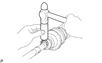
Using a brass bar and a hammer, tap on the output shaft bearing shaft snap ring.
-
-
INSPECT 5TH GEAR THRUST CLEARANCE
-
Using a feeler gauge, measure the 5th gear thrust clearance.
Standard clearance 0.1 to 0.3 mm (0.0039 to 0.0118 in.)
-
-
INSTALL SPEEDOMETER DRIVE (MTM) GEAR
-
Using a snap ring expander, install the speedometer drive gear ring to the output shaft.
-
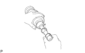
Install the inner race lock ball to the output shaft.
-
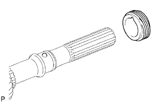
Install the speedometer drive gear to the output shaft.
-
Using a snap ring expander, install the speedometer drive gear ring to the output shaft.
-
-
INSPECT 3RD GEAR RADIAL CLEARANCE
-
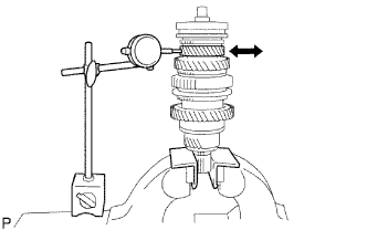
Using a did indicator, measure the 3rd gear radial clearance.
Standard clearance 0.008 to 0.034 mm (0.0003 to 0.00134 in.)
-
-
INSPECT 2ND GEAR RADIAL CLEARANCE
-
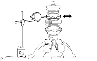
Using a dial indicator, measure the 2nd gear radial clearance.
Standard clearance 0.008 to 0.034 mm (0.0003 to 0.00134 in.)
-
-
INSPECT 1ST GEAR RADIAL CLEARANCE
-
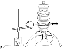
Using a dial indicator, measure the 1st gear radial clearance.
Standard clearance 0.009 to 0.056 mm (0.0004 to 0.00220 in.)
-