INPUT SHAFT DISASSEMBLY

-
REMOVE SYNCHRONIZER RING NO.1
-
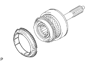
Remove the synchronizer ring No. 1.
-
-
REMOVE INPUT SHAFT BEARING
-
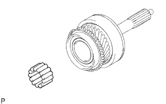
Remove the 13 input shaft bearing from the input shaft assembly.
-
-
REMOVE INPUT SHAFT FRONT BEARING
-
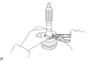
Using a snap ring expander, remove the front bearing shaft snap ring from the input shaft assembly.
-
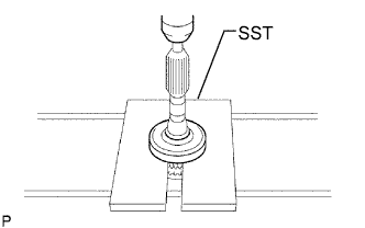
Using SST and a press, remove the input shaft front bearing from the input shaft.
- SST
- 09527-10011
-
-
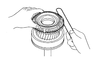
INSPECT SYNCHRONIZER RING NO.1
-

Coat the input shaft cone with gear oil. Check the braking effect of the synchronizer ring No. 1. Turn the synchronizer ring No. 1 one direction while pushing it to the input shaft cone. Check that the ring locks.
If the braking effect is insufficient, apply a small amount of the fine lapping compound between the synchronizer ring No. 1 and the input shaft cone. Lightly rub the synchronizer ring No. 1 and the input shaft cone together.
Note
Ensure the fine lapping compound is completely washed off after rubbing.
-
Check again the braking effect of the synchronizer ring No. 1.
-
Using a feeler gauge, measure the clearance between the synchronizer ring No. 1 back and the input shaft spline end.
Standard clearance 1.0 to 2.0 mm (0.0394 to 0.0787 in.) If the clearance is less than the minimum, replace the synchronizer ring No. 1 and apply a small amount of the fine lapping compound on the input shaft cone.
Note
Ensure the fine lapping compound is completely washed off after rubbing.
-