MANUAL TRANSMISSION UNIT REASSEMBLY

-
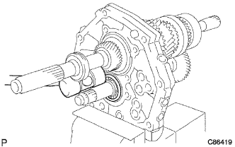
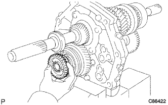
INSTALL OUTPUT SHAFT ASSEMBLY
-
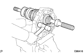
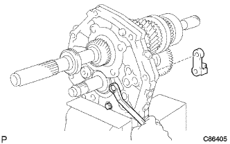
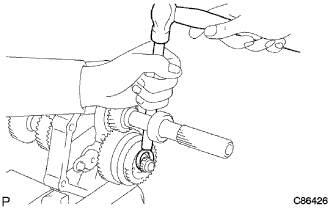
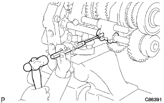
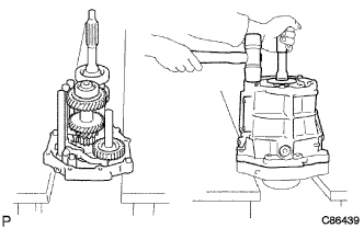
Install the output shaft assembly into the intermediate plate by pulling on the output shaft assembly and tapping on the intermediate plate.
-
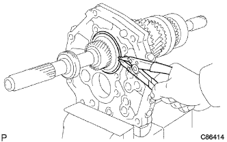
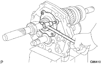
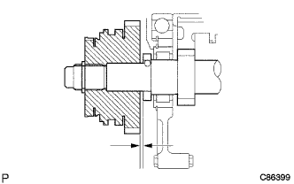
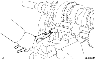
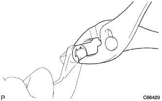
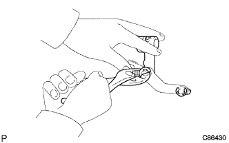
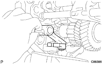
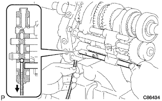
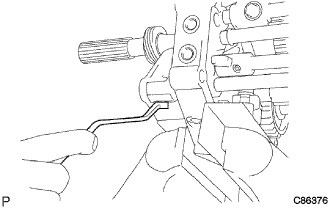
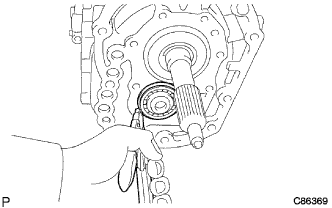
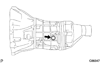
Using a snap ring expander, install the output shaft bearing shaft snap ring to the output shaft bearing RR.
Tech Tips
Be sure the output shaft bearing shaft snap ring is flush with the intermediate plate surface.
-
-
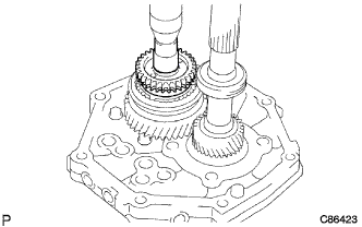
INSTALL INPUT SHAFT ASSEMBLY
-
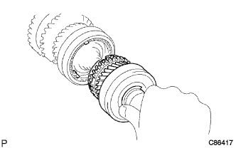
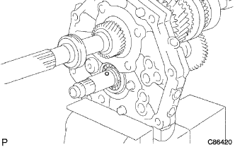
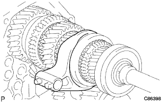
Coat the input shaft assembly and the synchronizer ring No. 1 with gear oil, install them to the output shaft.
-
-
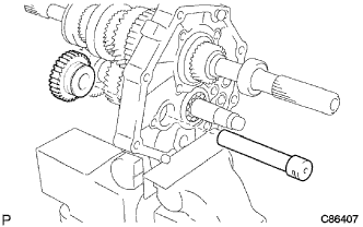
INSTALL COUNTER GEAR ASSEMBLY
-
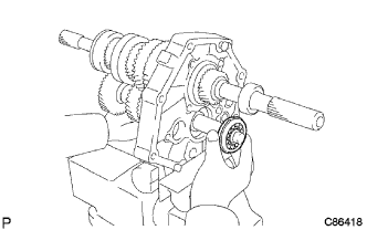
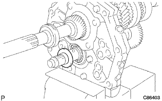
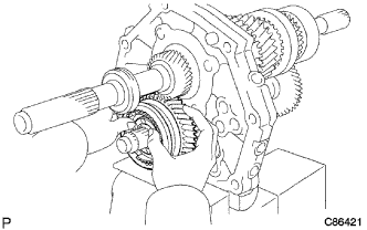
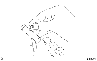
Temporarily install the counter gear assembly and a new counter shaft center bearing to the intermediate plate.
Note
Install so that the snap ring on the counter shaft center bearing will face to the rear side.
-
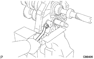
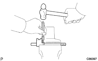
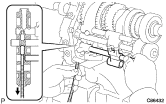
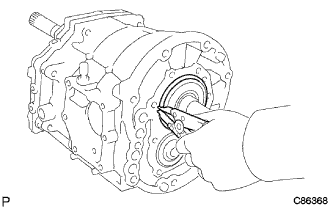
Using a plastic hammer, install the counter shaft center bearing to the intermediate plate with tapping outer race of the counter shaft center bearing.
Tech Tips
Hold the front side of the counter gear by hand.
-
-
INSTALL OUTPUT SHAFT REAR BEARING (MTM) RETAINER
-
Using "TORX" socket wrench T40, install the 4 screws and the output shaft rear bearing retainer to the intermediate palate.
- Torque:
- 18 N*m { 185 kgf*cm, 13 ft.*lbf }
-
-
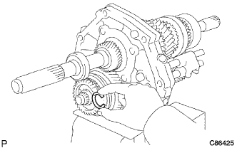
INSTALL REVERSE IDLER GEAR SUB-ASSEMBLY
-
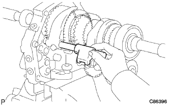
Install the reverse idler gear shaft and the reverse idler gear sub-assembly to the intermediate plate.
-
Install the bolt and the reverse idler gear shaft stopper to the intermediate plate.
- Torque:
- 17 N*m { 175 kgf*cm, 12 ft.*lbf }
-
-
INSTALL REVERSE SHIFT ARM BRACKET
-
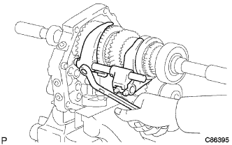
Install the 2 bolts and the reverse shift arm bracket to the intermediate plate.
- Torque:
- 18 N*m { 185 kgf*cm, 13 ft.*lbf }
-
-
INSTALL 5TH GEAR BEARING INNER RACE LOCK BALL
-
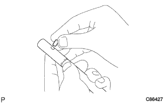
Install the 5th gear bearing inner race lock ball to the counter gear.
-
-
INSTALL 5TH GEAR THRUST WASHER
-
Install the 5th gear thrust washer to the counter gear.
-
-
INSTALL COUNTER SHAFT 5TH GEAR ASSEMBLY
-
Install the counter shaft 5th gear assembly to the counter gear.
-
Temporarily install the synchronizer ring No. 3 on the gear spline piece No. 5.
-
Dismount the intermediate plate from the vise.
-
Stand the manual transmission as shown.
-
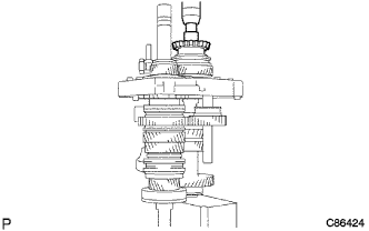
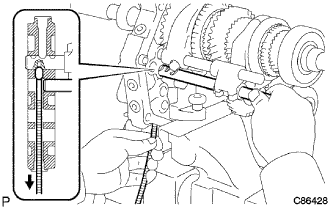
Using a press and a socket wrench 22 mm, install the gear spline piece No. 5 with the synchronizer ring No. 3 slots aligned with the shifting keys.
-
Mount the intermediate plate to the vise.
-
Select a counter gear rear shaft snap ring that will allow minimum axial play.
Counter gear rear shaft snap ring thickness Mark Thickness A 2.80 to 2.85 mm (0.110 to 0.112 in.) B 2.85 to 2.90 mm (0.112 to 0.114 in.) C 2.90 to 2.95 mm (0.114 to 0.116 in.) D 2.95 to 3.00 mm (0.116 to 0.118 in.) E 3.00 to 3.05 mm (0.118 to 0.120 in.) F 3.05 to 3.10 mm (0.120 to 0.122 in.) -
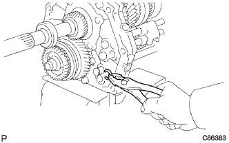
Using a brass bar and a hammer, install the counter gear rear shaft snap ring to the counter gear.
-
-
INSPECT COUNTER SHAFT 5TH GEAR THRUST CLEARANCE
-
Using a feeler gauge, inspect the counter shaft 5th gear thrust clearance.
Standard clearance 0.10 to 0.30 mm (0.0039 to 0.0118 in.) Maximum clearance 0.30 mm (0.0118 in.)
-
-
INSTALL GEAR SHIFT HEAD NO.1
-
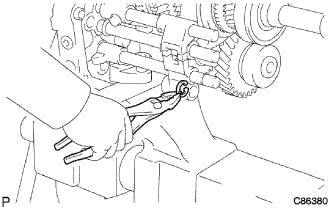
Install the gear shaft head to the gear shift fork shaft No. 1.
-
Using a pin punch and a hammer, drive in the shift lever shaft set slotted spring pin to the gear shift fork shaft No. 1.
-
-
INSTALL GEAR SHIFT FORK NO.2
-
Coat the gear shift fork No. 2 with gear oil, install it to the transmission hub sleeve No. 2.
-
-
INSTALL GEAR SHIFT FORK SHAFT NO.1
-
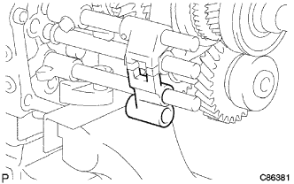
Install the gear shift fork shaft No. 1 through the gear shift fork No. 2, gear shift fork No. 1 and the intermediate plate.
-
Install the shift fork bolt to the gear shift fork No. 1.
- Torque:
- 20 N*m { 200 kgf*cm, 14 ft.*lbf }
-
-
INSTALL SHIFT INTER LOCK PIN NO.2
-
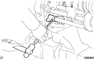
Coat the shift inter lock pin No. 2 with MP grease, install it into the gear shift fork shaft No. 2.
-
-
INSTALL GEAR SHIFT FORK SHAFT NO.2
-
Coat the shift inter lock pin No. 1 with MP grease.
-
Using a magnetic finger, install the shift inter lock pin No. 1 to the intermediate plate.
-
Install the gear shift fork shaft No. 2 through the gear shift fork No. 2 and the intermediate plate.
-
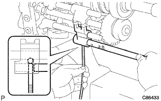
Using a pin punch and a hammer, drive the shift lever shaft set slotted spring pin to the gear shift fork No. 2.
-
Install the shift fork shaft snap ring to the gear shift fork shaft No. 2.
-
-
INSTALL REVERSE SHIFT ARM
-
Install the shift arm shoe shaft snap ring and the shift arm shoe to the reverse shift arm.
-
Install the reverse shift arm E-ring and the reverse shift fork to the reverse shift arm.
-
Install the reverse shift arm to the reverse shift arm bracket.
-
-
INSTALL SHIFT INTER LOCK PIN NO.2
-
Coat the shift inter lock pin No. 2 with MP grease, install it into the reverse shift fork shaft.
-
-
INSTALL REVERSE SHIFT FORK SHAFT
-
Coat the shift inter lock pin No. 1 with MP grease.
-
Using a magnetic finger, install the shift inter lock pin No. 1 to the intermediate plate.
-
Install the reverse shift fork shaft through the reverse shift fork and the intermediate plate.
-
Install the shift fork shaft snap ring to the reverse shift fork shaft.
-
Using a pin punch and a hammer, drive in the shift lever shaft set slotted spring pin to the reverse shift fork.
-
-
INSTALL REVERSE SHIFT HEAD
-
Install the reverse shift head to the reverse shift fork shaft.
-
Install the reverse shift head ring to the reverse shift fork shaft.
-
-
INSTALL GEAR SHIFT FORK SHAFT NO.4
-
Coat the reverse shift restrict ball with MP grease.
-
Using a magnetic finger, install the reverse shift restrict ball to the reverse shift head.
-
Install the gear shift fork shaft No. 4 through the reverse shift head.
-
Coat the shift inter lock ball No. 1 with MP grease.
-
Using a magnetic finger, install the shift inter lock ball No. 1 to the intermediate plate.
-
Install gear shift fork shaft No. 4 through the gear shift fork No. 3 and the intermediate plate.
-
Install the shift fork bolt to the gear shift fork No. 3.
- Torque:
- 20 N*m { 200 kgf*cm, 14 ft.*lbf }
-
Install the reverse shift head ring to the gear shift fork shaft No. 4.
-
-
INSTALL SHIFT DETENT BALL NO.2
-
Coat the shift detent ball No. 2 with MP grease.
-
Install the shift detent ball No. 2 and the shift detent ball compression spring to the intermediate plate.
-
Coat the shift detent ball spring seat No. 2 with sealant.
Sealant Toyota Genuine Adhesive 1344, Three Bond 1344 or equivalent -
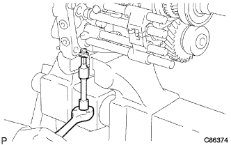
Using "TORX" socket wrench T40, install the shift detent ball spring seat No. 2 to the intermediate plate.
- Torque:
- 19 N*m { 190 kgf*cm, 14 ft.*lbf }
-
-
INSTALL SHAFT DETENT BALL
-
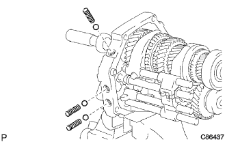
Coat the 3 shift detent balls with MP grease, install them and the 3 shift detent ball low side compression springs to the intermediate plate.
-
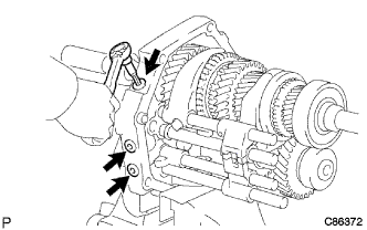
Coat the 3 shift detent ball spring seats No. 1 with sealant.
Sealant Toyota Genuine Adhesive 1344, Three Bond 1344 or equivalent -
Using "TORX" socket wrench T40, install the 3 shift detent ball spring seats No. 1 to the intermediate plate.
- Torque:
- 19 N*m { 194 kgf*cm, 14 ft.*lbf }
-
-
INSTALL MANUAL TRANSMISSION CASE
-
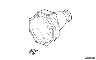
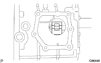
Apply seal packing to the manual transmission case as shown.
Sealant Toyota Genuine Seal Packing 1281, Three Bond 1281 or equivalent -
Stand the intermediate plate as shown.
-
Using a plastic hammer, install the manual transmission case to the intermediate plate as shown.
-
-
INSTALL COUNTER GEAR FRONT BEARING SNAP RING NO.1
-
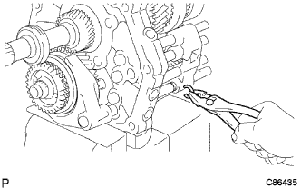
Using a snap ring expander, install the counter gear front bearing snap ring No. 1 to the counter gear front bearing.
-
-
INSTALL FRONT BEARING SHAFT SNAP RING
-
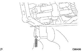
Using a snap ring expander, install the front bearing shaft snap ring to the input shaft shim.
-
-
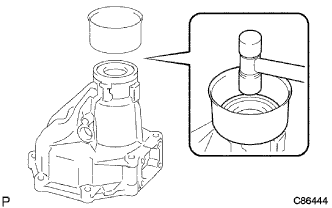
INSTALL TRANSMISSION FRONT BEARING RETAINER OIL SEAL
-
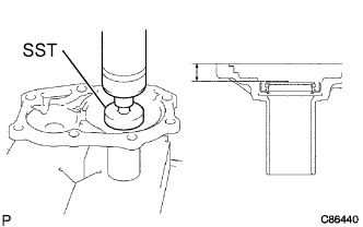
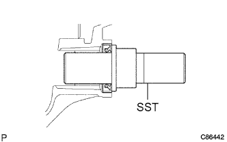
Using SST, press in a new transmission front bearing retainer oil seal to the front bearing retainer.
- SST
- 09950-60010 ( 09952-06010, 09951-00440 )
Oil seal depth 12.2 to 13.2 mm (0.480 to 0.520 in.) Transmission case installation surface
-
-
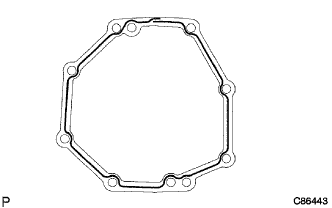
INSTALL BEARING RETAINER FRONT (MTM)
-
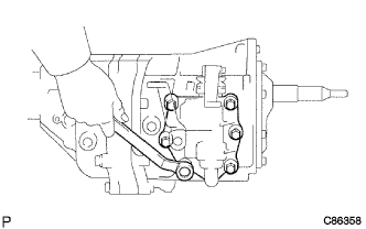
Install the bearing retainer front with a new transmission front bearing retainer gasket to the manual transmission case.
-
Apply sealant to the bolt threads.
Sealant Toyota Genuine Adhesive 1344, Three Bond 1344 or equivalent -
Install the 8 bolts to the manual transmission case.
- Torque:
- 17 N*m { 170 kgf*cm, 12 ft.*lbf }
-
-
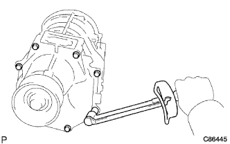
INSTALL MANUAL TRANSMISSION EXTENSION HOUSING OIL SEAL
-
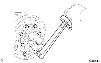
Using SST, drive in a new manual transmission extension housing oil seal to the extension housing.
- SST
- 09325-20010
-
-
INSTALL EXTENSION HOUSING OIL RECEIVER PIPE NO.1
-
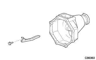
Install the extension housing oil receiver pipe No. 1 to the extension housing.
-
-
INSTALL EXTENSION HOUSING OIL RECEIVER PIPE NO.2
-
Install the bolt and the extension housing oil receiver pipe No. 2 to the extension housing.
- Torque:
- 11 N*m { 115 kgf*cm, 8 ft.*lbf }
-
-
INSTALL TRANSMISSION (MTM) MAGNET
-
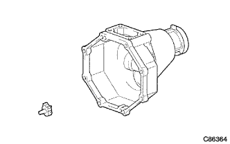
Install the transmission magnet to the extension housing.
-
-
INSTALL EXTENSION HOUSING DUST(MTM) DEFLECTOR
-
Using a plastic hammer, install the extension housing dust deflector to the extension housing.
-
-
INSTALL EXTENSION (MTM) HOUSING SUB-ASSEMBLY
-
Apply seal packing to the extension housing as shown.
Seal Packing Toyota Genuine Seal Packing 1281, Three Bond 1281 or equivalent -
Install 8 bolts and the extension housing to the manual transmission case.
- Torque:
- 37 N*m { 380 kgf*cm, 27 ft.*lbf }
-
-
INSTALL SHIFT LEVER SHAFT HOUSING ASSEMBLY
-
Shift the gear shift fork No. 2, gear shift head and the reverse shift head to the neutral position.
-
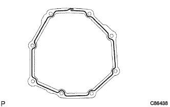
Install a new shift lever shaft housing gasket to the manual transmission case.
-
Apply sealant to the 4 yellow bolts threads and the 2 blueish silver bolts threads.
-
Install the 6 bolts and the shift lever shaft housing assembly to the manual transmission case.
- Torque:
- 17 N*m { 170 kgf*cm, 12 ft.*lbf }
-
-
INSTALL CLUTCH HOUSING
-
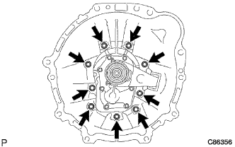
Install the clutch housing.
-
Apply liquid sealer to the bolt threads.
Sealant Toyota Genuine Adhesive 1344, Three Bond 1344 or equivalent -
Install the 9 bolts to the clutch housing.
- Torque:
- 37 N*m { 380 kgf*cm, 27 ft.*lbf }
-
-
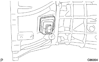
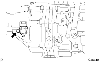
INSTALL BACK-UP LAMP SWITCH ASSEMBLY
-
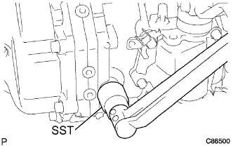
Using SST, install the back-up lamp switch assembly to the manual transmission case.
- SST
- 09817-16011
- Torque:
- 37 N*m { 380 kgf*cm, 27 ft.*lbf }
-
-
INSTALL CLUTCH RELEASE FORK BOOT
-
Install the clutch release fork boot to the manual transmission case.
-
-
INSTALL RELEASE FORK SUPPORT
-
Install the release fork support to the manual transmission case.
- Torque:
- 37 N*m { 380 kgf*cm, 27 ft.*lbf }
-
-
INSTALL CLUTCH RELEASE BEARING ASSEMBLY
-
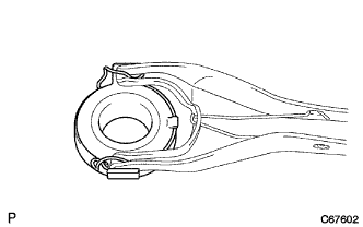
Coat the clutch release bearing assembly with release hub grease, install it to the clutch release fork sub-assembly.
-
-
INSTALL CLUTCH RELEASE FORK SUB-ASSEMBLY
-
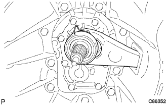
Install the clutch release fork sub-assembly to the input shaft.
-
Apply molybdenum disulphide lithium base grease to the input shaft spline.
-
-
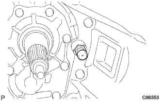
INSTALL SPEEDOMETER DRIVEN (MTM) GEAR SUB-ASSEMBLY
-
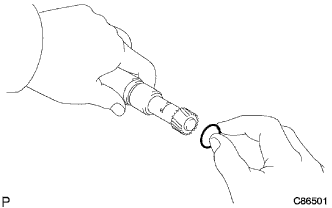
Install a new speedometer sensor O-ring to the speedometer sensor.
-
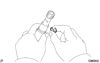
Install the speedometer driven gear and the speedometer shaft sleeve clip to the speedometer sensor.
-
Install the speedometer driven gear sub-assembly to the extension housing with the bolt.
- Torque:
- 11 N*m { 115 kgf*cm, 8 ft.*lbf }
-
-
INSTALL DRAIN (MTM) PLUG SUB-ASSEMBLY
-
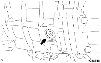
Using a hexagon wrench 10 mm, install the drain plug with a new drain plug gasket to the manual transmission case.
- Torque:
- 37 N*m { 380 kgf*cm, 27 ft.*lbf }
-
-
INSTALL MANUAL TRANSMISSION FILLER PLUG
-
Install the manual transmission filler plug with a new manual transmission filler plug gasket to the manual transmission case.
- Torque:
- 37 N*m { 380 kgf*cm, 27 ft.*lbf }
-