MANUAL TRANSMISSION UNIT DISASSEMBLY

-
REMOVE MANUAL TRANSMISSION FILLER PLUG
-
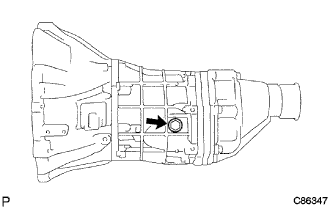
Remove the manual transmission filler plug and the manual transmission filler plug gasket from the manual transmission case.
-
-
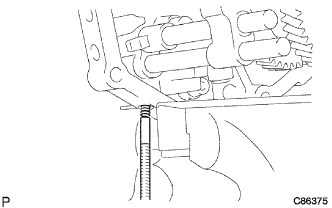
REMOVE DRAIN (MTM) PLUG SUB-ASSEMBLY
-
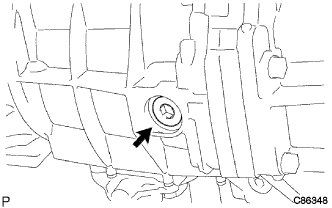
Using a hexagon wrench 10 mm, remove the drain plug and the drain plug gasket from the manual transmission case.
-
-
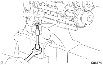
REMOVE SPEEDOMETER DRIVEN (MTM) GEAR SUB-ASSEMBLY
-
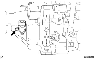
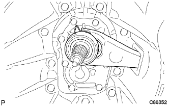
Remove the bolt and the speedometer driven gear sub-assembly.
-
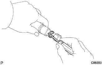
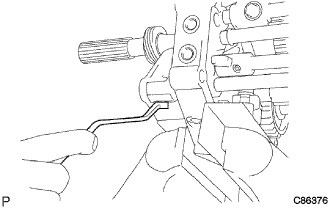
Using a screwdriver, remove the speedometer shaft sleeve clip and the speedometer driven gear from the speedometer sensor.
-
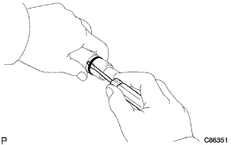
Using a screwdriver, remove the speedometer sensor O-ring from the speedometer sensor.
-
-
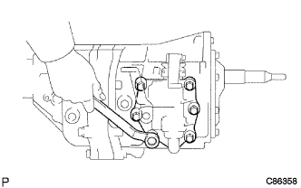
REMOVE CLUTCH RELEASE FORK SUB-ASSEMBLY
-
Remove the clutch release fork sub-assembly and the clutch release bearing assembly from the manual transmission case.
-
-
REMOVE CLUTCH RELEASE BEARING ASSEMBLY
-
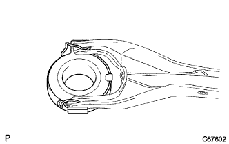
Remove the release bearing hub clip and the clutch release bearing assembly from the clutch release fork sub-assembly.
-
-
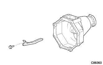
REMOVE RELEASE FORK SUPPORT
-
Remove the clutch release fork support from the manual transmission case.
-
-
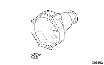
REMOVE CLUTCH RELEASE FORK BOOT
-
Remove the clutch release fork boot from the manual transmission case.
-
-
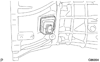
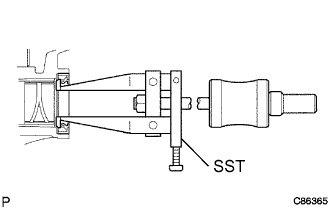
REMOVE BACK-UP LAMP SWITCH ASSEMBLY
-
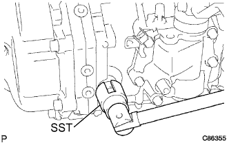
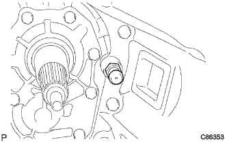
Using SST, remove the back-up lamp switch assembly and gasket from the manual transmission case.
- SST
- 09817-16011
-
-
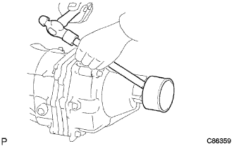
REMOVE CLUTCH HOUSING
-
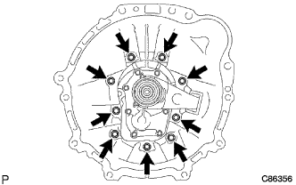
Remove the 9 bolts.
-
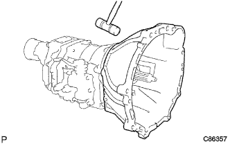
Tap on the circumference of the clutch housing with a plastic hammer to remove the clutch housing from the manual transmission case.
-
-
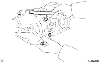
REMOVE SHIFT LEVER SHAFT HOUSING ASSEMBLY
-
Remove the 6 bolts and the shift lever shaft housing assembly from the manual transmission case.
-
Remove the shift lever shaft housing gasket from the manual transmission case.
-
-
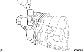
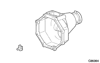
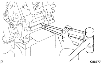
REMOVE EXTENSION HOUSING DUST (MTM) DEFLECTOR
-
Using a brass bar and a hammer, remove the extension housing dust deflector from the extension housing.
-
-
REMOVE EXTENSION (MTM) HOUSING SUB-ASSEMBLY
-
Remove the 8 bolts.
-
Using a plastic hammer, remove the extension housing from the manual transmission case.
-
-
REMOVE TRANSMISSION (MTM) MAGNET
-
Remove the transmission magnet from the extension housing.
-
-
REMOVE EXTENSION HOUSING OIL RECEIVER PIPE NO.2
-
Remove the bolt and the extension housing oil receiver pipe No. 2 from the extension housing.
-
-
REMOVE EXTENSION HOUSING OIL RECEIVER PIPE NO.1
-
Remove the extension housing oil receiver pipe No. 1 from the extension housing.
-
-
REMOVE MANUAL TRANSMISSION EXTENSION HOUSING OIL SEAL
-
Using SST, remove the manual transmission extension housing oil seal from the extension housing.
- SST
- 09308-00010
-
-
REMOVE BEARING RETAINER FRONT (MTM)
-
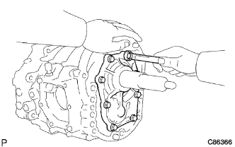
Remove the 8 bolts.
-
Remove the bearing retainer front and the transmission front bearing retainer gasket from the manual transmission case.
-
-
REMOVE TRANSMISSION FRONT BEARING RETAINER OIL SEAL
-
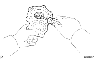
Using a screwdriver, remove the transmission front bearing retainer oil seal from the bearing retainer front.
-
-
REMOVE FRONT BEARING SHAFT SNAP RING
-
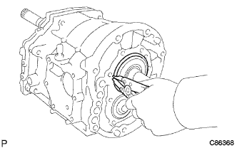
Using a snap ring expander, remove the front bearing shaft snap ring from the manual transmission case.
-
-
REMOVE COUNTER GEAR FRONT BEARING SNAP RING NO.1
-
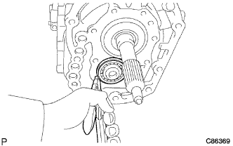
Using a snap ring expander, remove the counter gear front bearing snap ring No. 1 from the manual transmission case.
-
-
REMOVE MANUAL TRANSMISSION CASE
-
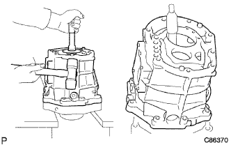
Stand the manual transmission assembly as shown.
-
Using a plastic hammer, carefully tap off the manual transmission case.
-
Remove the manual transmission case from the intermediate plate as shown.
-
-
FIX INTERMEDIATE PLATE
-
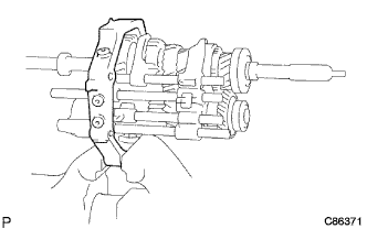
Fix the intermediate plate in a vise.
-
-
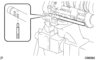
REMOVE SHAFT DETENT BALL
-
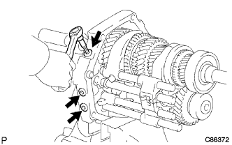
Using "TORX" socket wrench T40, remove the 3 shift detent ball spring seats No. 1 from the intermediate plate.
-
Using a magnetic finger, remove the 3 shift detent ball low side compression springs and the 3 shift detent balls from the intermediate plate.
-
-
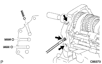
REMOVE SHIFT DETENT BALL NO.2
-
Using "TORX" socket wrench T40, remove the shift detent ball spring seat No. 2 from the intermediate plate.
-
Using a magnetic finger, remove the shift detent ball compression spring and the shift detent ball No. 2 from the intermediate plate.
-
-
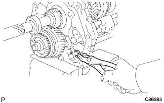
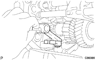
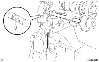
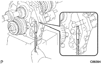
REMOVE GEAR SHIFT FORK SHAFT NO.4
-
Remove the shift fork bolt from the gear shift fork No. 3.
-
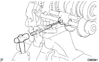
Using 2 screwdrivers and a hammer, remove the reverse shift head ring from the gear shift fork shaft No. 4.
-
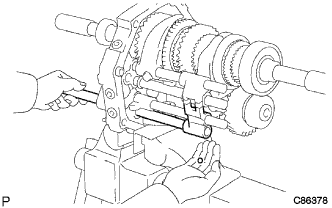
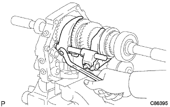
Remove the reverse shift restrict ball from the reverse shift head.
-
Remove the gear shift fork shaft No. 4, shift inter lock ball No. 1 and the gear shift fork No. 3 from the intermediate plate.
-
-
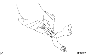
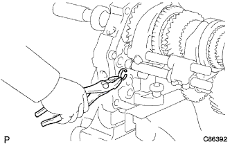
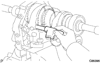
REMOVE REVERSE SHIFT HEAD
-
Remove the reverse shift head ring from the reverse shift fork shaft.
-
Remove the reverse shift head from the reverse shift fork shaft.
-
-
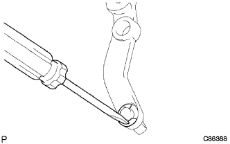
REMOVE SHIFT INTER LOCK PIN NO.2
-
Using a magnetic finger, remove the shift inter lock pin No. 2 from the reverse shift fork shaft.
-
-
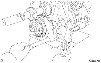
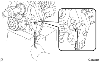
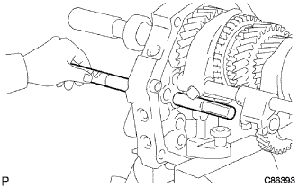
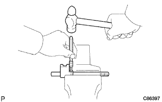
REMOVE REVERSE SHIFT FORK SHAFT
-
Remove the shift fork shaft snap ring from the reverse shift fork shaft.
-
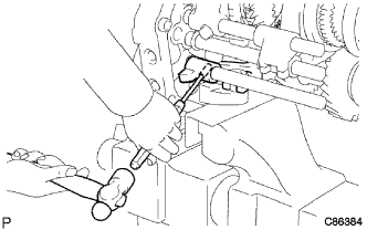
Using a pin punch and a hammer, drive out the shift lever shaft set slotted spring pin from the reverse shift fork.
-
Remove the reverse shift fork shaft from the intermediate plate.
-
-
REMOVE REVERSE SHIFT ARM
-
Remove the reverse shift arm assembly from the reverse shift arm bracket.
-
Using a screwdriver, remove the reverse shift arm E-ring.
-
Remove the reverse shift fork from the reverse shift arm.
-
Using a screwdriver, remove the shift arm shoe shaft snap ring.
-
Remove the shift arm shoe from the reverse shift arm.
-
-
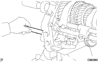
REMOVE SHIFT INTER LOCK PIN NO.1
-
Using a magnetic finger, remove the shift inter lock pin No. 1 from the intermediate plate.
-
-
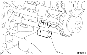
REMOVE SHIFT INTER LOCK PIN NO.2
-
Using a magnetic finger, remove the shift inter lock pin No. 2 from the gear shift fork shaft No. 2.
-
-
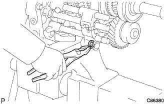
REMOVE GEAR SHIFT FORK SHAFT NO.2
-
Using a pin punch and a hammer, drive out the shift lever shaft set slotted spring pin from the gear shift fork No. 2.
-
Remove the shift fork shaft snap ring from the gear shift fork shift No. 2.
-
Remove the gear shift fork shaft No. 2 from the intermediate plate.
-
-
REMOVE SHIFT INTER LOCK PIN NO.1
-
Using a magnetic finger, remove the shift inter lock pin No. 1 from the intermediate plate.
-
-
REMOVE GEAR SHIFT FORK SHAFT NO.1
-
Remove the shift fork bolt from the gear shift fork No. 1.
-
Remove the gear shift fork shaft No. 1 assembly and the gear shift fork No. 1 from the intermediate plate.
-
Using a pin punch and a hammer, drive out the shift lever shaft set slotted spring pin from the gear shift head No. 1.
-
Remove the gear shift head No. 1 from the gear shift fork shaft No. 1.
-
-
REMOVE GEAR SHIFT FORK NO.2
-
Remove the gear shift fork No. 2 from the transmission hub sleeve No. 2.
-
-
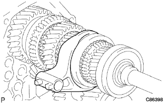
INSPECT COUNTER SHAFT 5TH GEAR THRUST CLEARANCE
-
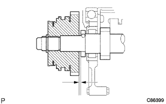
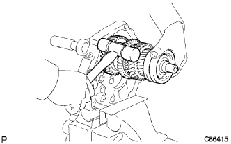
Using a feeler gauge, inspect the counter shaft 5th gear thrust clearance.
Standard clearance 0.10 to 0.30 mm (0.0039 to 0.0118 in.) Maximum clearance 0.30 mm (0.0118 in.)
-
-
REMOVE COUNTER SHAFT 5TH GEAR ASSEMBLY
-
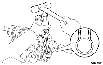
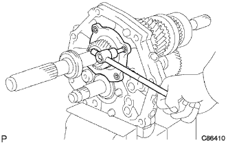
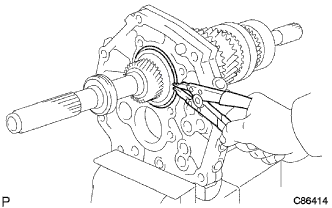
Using 2 screwdrivers and a hammer, top out the counter gear rear shaft snap ring from the counter gear.
-
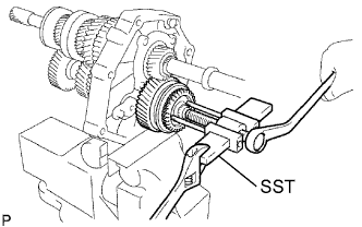
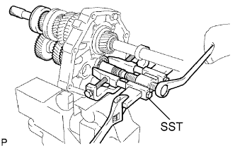
Using SST, remove the gear spline piece No. 5 and the synchronizer ring No. 3 from the counter gear.
- SST
- 09950-50013 ( 09951-05010, 09952-05010, 09953-05010, 09954-05021 )
-
Remove the counter shaft 5th gear assembly and the counter 5th gear bearing from the counter gear.
-
-
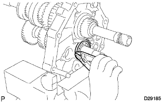
REMOVE 5TH GEAR THRUST WASHER
-
Remove the 5th gear thrust washer from the counter gear.
-
Using a magnetic finger, remove the 5th gear bearing inner race lock ball from the counter gear.
-
-
REMOVE REVERSE SHIFT ARM BRACKET
-
Remove the 2 bolts and the reverse shift arm bracket from the intermediate plate.
-
-
REMOVE REVERSE IDLER GEAR SUB-ASSEMBLY
-
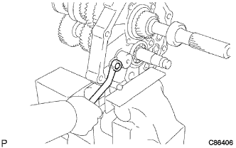
Remove the bolt and the reverse idler gear shaft stopper from the intermediate plate.
-
Remove the reverse idler gear shaft and the reverse idler gear sub-assembly from the intermediate plate.
-
-
INSPECT REVERSE IDLER GEAR RADIAL CLEARANCE
-
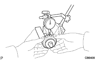
Using a dial indicator, inspect the reverse idler gear radial clearance.
Standard clearance 0.04 to 0.08 mm (0.0016 to 0.0031 in.) Maximum clearance 0.13 mm (0.0051 in.)
-
-
INSPECT REVERSE IDLER GEAR SUB-ASSEMBLY
-
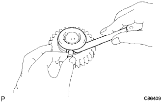
Using a feeler gauge, inspect the clearance between the reverse idler gear and the shift arm shoe.
Standard clearance 0.05 to 0.28 mm (0.0020 to 0.0110 in.) Maximum clearance 0.5 mm (0.0197 in.)
-
-
REMOVE OUTPUT SHAFT REAR BEARING (MTM) RETAINER
-
Using "TORX" socket wrench T40, remove the 4 screws and the output shaft rear bearing retainer from the intermediate plate.
-
-
REMOVE COUNTER GEAR ASSEMBLY
-
Using a snap ring expander, remove the counter shaft center bearing snap ring from the counter shaft center bearing.
-
Using SST, remove the counter shaft center bearing and the counter gear assembly from the intermediate plate.
- SST
- 09950-40011 ( 09951-04010, 09952-04010, 09953-04010, 09954-04010, 09955-04011, 09958-04011 )
-
-
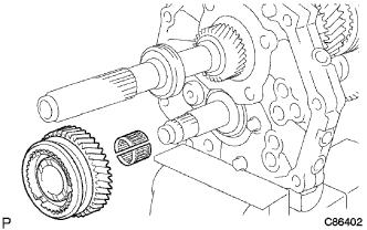
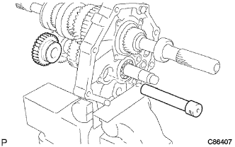
REMOVE INPUT SHAFT ASSEMBLY
-
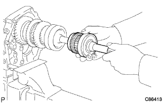
Remove the input shaft assembly with the 13 input shaft bearings and the synchronizer ring No. 1 from the output shaft.
-
-
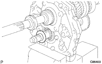
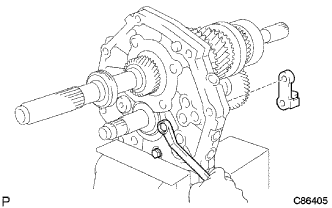
REMOVE OUTPUT SHAFT ASSEMBLY
-
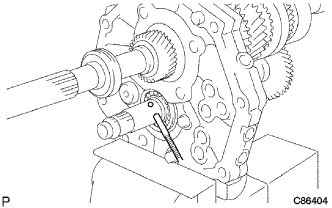
Using a snap ring expander, remove the output shaft bearing shaft snap ring from the output shaft bearing RR.
-
Remove the output shaft assembly from the intermediate plate by pulling on the output shaft assembly and tapping on the intermediate plate with a plastic hammer.
-