MANUAL TRANSMISSION UNIT REASSEMBLY

-
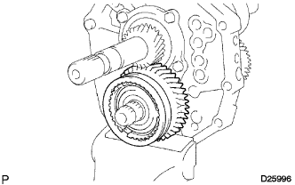
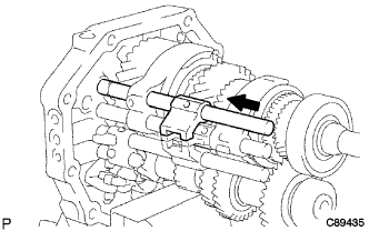
INSTALL OUTPUT SHAFT ASSEMBLY
-
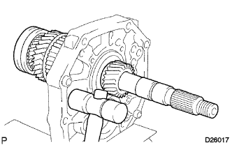
Apply gear oil to the sliding part of the output shaft assembly.
-
Using a plastic hammer, install the output shaft assembly with tapping the intermediate plate.
-
-
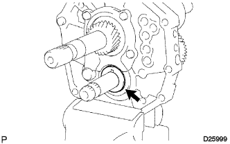
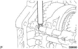
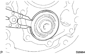
INSTALL OUTPUT SHAFT BEARING SHAFT SNAP RING
-
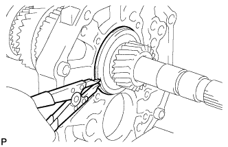
Using a snap ring expander, install the output shaft bearing shaft snap ring to the output shaft.
-
-
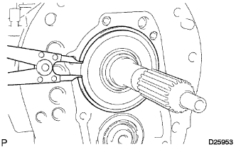
INSTALL INPUT SHAFT ASSEMBLY
-
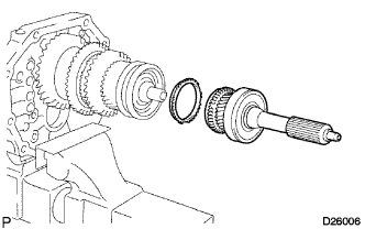
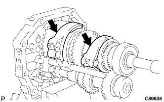
Apply gear oil to the input shaft assembly and the synchronizer ring No. 2, and install them to the output shaft.
Note
-
Install with aligning the groove of the synchronizer ring No. 2 with the position of the shifting key.
-
Check that the input shaft assembly rotates slightly.
-
-
-
INSTALL COUNTER GEAR ASSEMBLY
-
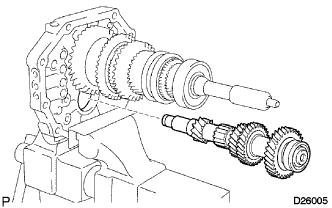
Temporarily install the counter gear assembly to the intermediate plate.
-
-
INSTALL COUNTER SHAFT CENTER BEARING
-
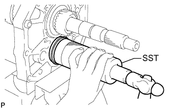
Using SST and a hammer, install a new counter shaft center bearing to the intermediate plate.
- SST
- 09316-60011 ( 09316-00011 )
Tech Tips
Install the bearing while the tip of the counter gear is tapped on with a plastic hammer, so that the counter gear assembly will not hit the side wall of the output shaft gear by being pushed forward at the time of installation the bearing.
-
-
INSTALL REVERSE IDLER GEAR SUB-ASSEMBLY
-
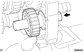
Apply gear oil to each sliding part of the reverse idler gear and the reverse idler gear shaft, and install them to the intermediate plate.
Note
Face the groove side of the reverse idler shaft to the rear side and install from the rear side.
-
-
INSTALL OUTPUT SHAFT REAR BEARING (MTM) RETAINER
-
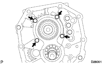
Install the transmission output shaft rear bearing retainer inserting to the groove of the reverse idler gear shaft with 4 bolts.
- Torque:
- 18 N*m { 184 kgf*cm, 13 ft.*lbf }
-
-
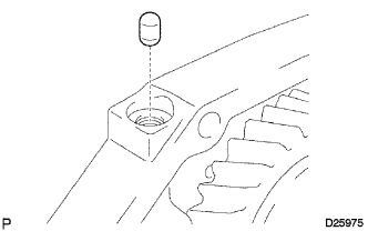
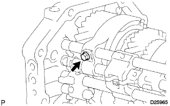
INSTALL 5TH GEAR THRUST WASHER PIN
-
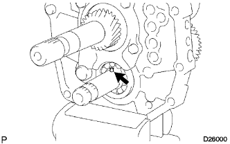
Apply MP grease to the 5th gear trust washer pin, and install it to the counter gear.
-
-
INSTALL 5TH GEAR THRUST WASHER
-
Apply gear oil to the 5th gear thrust washer and install it to the counter gear.
Note
Install the thrust washer so that its side of chamfer will face to the front side.
-
-
INSTALL TRANSMISSION HUB SLEEVE NO.3
-
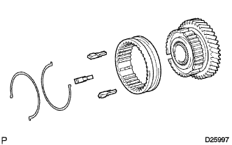
Apply gear oil to the sliding part of the transmission hub sleeve No. 3 and install it to the counter shaft 5th gear.
Note
Be sure of the direction of the transmission hub sleeve No. 3 and the counter shaft 5th gear.
-
Install the 3 synchromesh shifting keys No. 3 and the 2 synchromesh shifting key spring to the counter shaft 5th gear.
Note
Do not set both opening of the shifting key springs in the opposite position.
-
-
INSTALL COUNTER 5TH GEAR BEARING
-
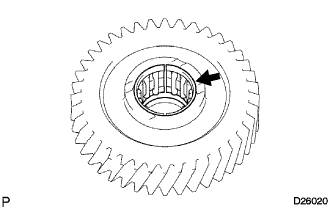
Apply gear oil to the counter 5th gear bearing and install it to the counter gear.
-
-
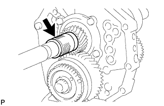
INSTALL COUNTER SHAFT 5TH GEAR
-
Apply gear oil to the counter shaft 5th gear and the transmission hub sleeve No. 3 assembly, and install them to the counter gear.
-
-
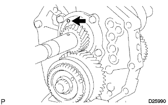
INSTALL SYNCHRONIZER RING NO.3
-
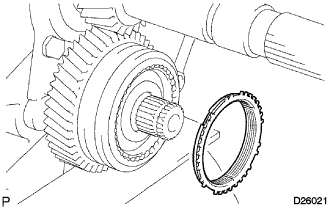
Apply gear oil to the synchronizer ring No. 3 and install it to the counter gear.
Note
Match the key groove of the synchronize ring No. 3 with the position of the synchromesh shifting key No. 3.
-
-
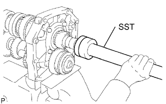
INSTALL GEAR SPLINE PIECE NO.5
-
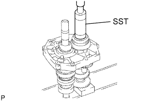
Using SST and a press, install the gear spline piece No. 5 to the counter gear.
- SST
- 09316-60011 ( 09316-00011 )
Note
Check that the gear rotate lightly.
-
-
INSTALL COUNTER GEAR REAR SHAFT SNAP RING
-
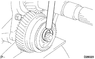
Select the counter gear rear shaft snap ring so that the thrust gap between the gear spline piece No. 5 and the counter gear rear shaft snap ring is within the specification, and using a brass bar and a hammer, install it to the counter gear.
Standard clearance 0.1 mm (0.0039 in.) or less Mark Thickness mm (in.) A 2.80 to 2.85 (0.1102 to 0.1122) B 2.85 to 2.90 (0.1122 to 0.1141) C 2.90 to 2.95 (0.1141 to 0.1160) D 2.95 to 3.00 (0.1160 to 0.1181) E 3.00 to 3.05 (0.1181 to 0.1200) F 3.05 to 3.10 (0.1200 to 0.1220) G 3.10 to 3.15 (0.1220 to 0.1240)
-
-
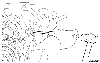
INSPECT COUNTER SHAFT 5TH GEAR THRUST CLEARANCE
-
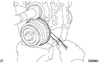
Using a feeler gauge, check the counter shaft 5th gear thrust clearance.
Standard clearance 0.10 to 0.35 mm (0.0039 to 0.0138 in.)
-
-
INSPECT COUNTER SHAFT 5TH GEAR RADIAL CLEARANCE
-
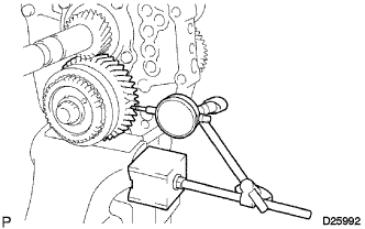
Using a dial indicator, check the radial clearance of the counter shaft 5th gear.
Standard clearance 0.015 to 0.068 mm (0.00059 to 0.0027 in.) If the value is not within the specification, replace the counter shaft 5th gear bearing with a new one.
-
-
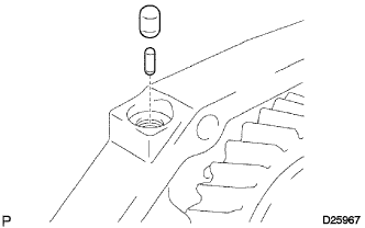
INSTALL SPEEDOMETER DRIVE GEAR (MTM) KEY OR BALL
-
Apply MP grease to the speedometer drive gear ball and install it to the output shaft.
-
-
INSTALL SPEEDOMETER DRIVE (MTM) GEAR
-
Apply gear oil to the speedometer drive gear and install it to the output shaft.
-
-
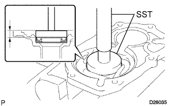
INSTALL OUTPUT SHAFT REAR BEARING
-
Using SST and a press, install a new output shaft rear bearing to the output shaft.
- SST
- 09309-35010
-
-
INSTALL REVERSE SHIFT ARM BRACKET
-
Install the reverse shift arm bracket to the intermediate plate with the 2 bolts.
- Torque:
- 18 N*m { 184 kgf*cm, 13 ft.*lbf }
-
-
INSTALL REVERSE SHIFT FORK
-
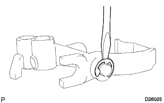
Install the reverse shift arm to the reverse shift fork. Using a screwdriver and a hammer, install a new reverse shift arm end shaft ring.
-
Install the tip of the reverse shift arm to the reverse idler gear. Align the cut end of the reverse shift arm with the reverse shift arm bracket pin and install them.
-
-
INSTALL GEAR SHIFT FORK SHAFT NO.4
-
Install the reverse shift fork compression spring and the reverse shift fork ball to the reverse shift fork.
-
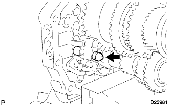
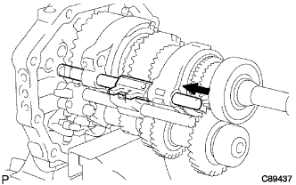
Apply gear oil to the sliding part of gear shift fork shaft No. 4.
-
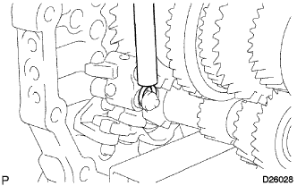
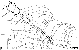
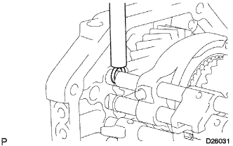
Using a screwdriver, install the gear shift fork shaft No. 4 with pushing the reverse shift fork ball lightly.
-
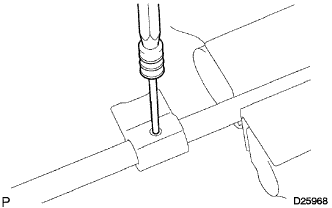
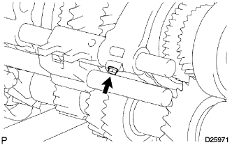
Using a brass bar and a hammer, install the shift fork shaft snap ring to the gear shift fork shaft No. 4.
-
-
INSTALL GEAR SHIFT HEAD NO.1
-
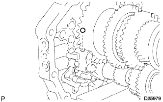
Apply gear oil to the gear shift head No. 1 and install it to the reverse shift fork shaft.
-
Using a pin punch (5 mm) and a hammer, install the shift head slotted pin to the reverse shift fork shaft.
-
-
INSTALL REVERSE SHIFT FORK SHAFT
-
Install the reverse shift fork ball to the reverse shift fork.
-
Install the shift interlock roller No. 1 to the intermediate plate.
-
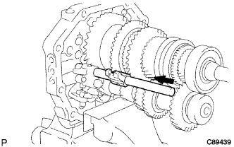
Install the gear shift fork No. 3 to the transmission hub sleeve, and install the reverse shift fork shaft to the intermediate plate from the front side.
-
Using a brass bar and a hammer, install the shift fork shaft snap ring to the reverse shift fork shaft.
-
Using a pin punch (5 mm) and a hammer, install the shift lever shaft set slotted pin to the reverse shift fork shaft.
-
-
INSTALL GEAR SHIFT FORK SHAFT NO.2
-
Install shift interlock roller No. 1 to the intermediate plate.
-
Install the gear shift fork No. 1 to the reverse gear.
-
Install the gear shift fork No. 2 to the transmission hub sleeve No. 2.
-
Install the gear shift head No. 2 and the gear shift fork shaft No. 2 to the intermediate plate from the front side.
-
Using a pin punch (5 mm) and a hammer, install the shift head slotted pin to the shift fork shaft No. 2.
-
Install the shift fork bolt to the gear shift fork No. 2.
- Torque:
- 19.5 N*m { 199 kgf*cm, 14 ft.*lbf }
-
Using a brass bar and a hammer, install the shift fork shaft snap ring to the gear shift fork shaft No. 2.
-
-
INSTALL SHIFT FORK SHAFT STOPPER
-
Install the shift fork shaft stopper to the gear shift fork shaft No. 2.
-
Using a pin punch (5 mm) and a hammer, install the shift fork shaft stopper slotted pin to the gear shift fork shaft No. 2.
-
-
INSTALL GEAR SHIFT HEAD NO.1
-
Apply gear oil to the gear shift head No. 1 and install it to the shift fork shaft No. 1.
-
Using a pin punch (5 mm) and a hammer, install the shift head slotted pin to the shift fork shaft No. 1.
-
-
INSTALL GEAR SHIFT FORK SHAFT NO.1
-
Install the shift interlock roller No. 1 and the shift interlock pin No. 1 to the intermediate plate.
-
Apply gear oil to the gear shift fork shaft No. 1 and install it to the intermediate plate from the front side.
-
Install the shift fork bolt to the gear shift fork No. 1.
- Torque:
- 19.5 N*m { 199 kgf*cm, 14 ft.*lbf }
-
Using a brass bar and a hammer, install the shift fork shaft snap ring to the gear shift fork shaft No. 1.
-
-
INSTALL SHIFT FORK SHAFT STOPPER
-
Install the shift fork shaft stopper to the gear shift fork shaft No. 1.
-
Using a pin punch (5 mm) and a hammer, install the shift fork shaft stopper slotted pin to the gear shift fork shaft No. 1.
-
-
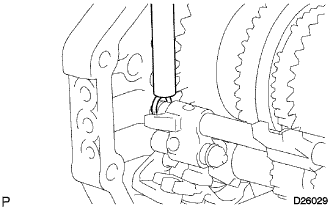
INSTALL SHIFT DETENT BALL SPRING SEAT NO.1
-
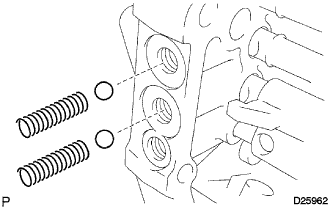
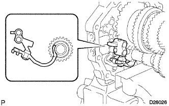
Install the 2 shift detent ball low side springs and the 2 shift detent balls to the intermediate plate.
-
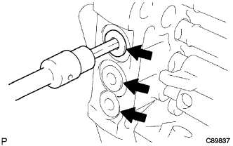
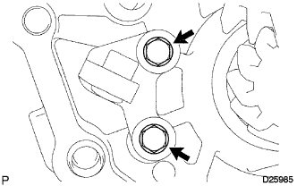
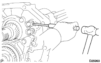
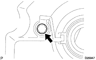
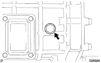
Using hexagon wrench, install the 3 shift detent ball spring seats No. 1 to the intermediate plate.
- Torque:
- 18.5 N*m { 189 kgf*cm, 14 ft.*lbf }
-
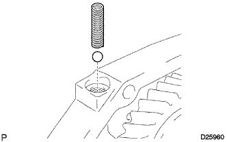
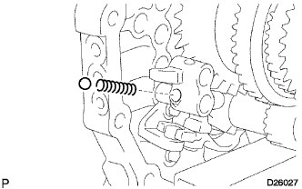
Install the shift detent ball low side spring and the shift detent ball to the intermediate plate.
-
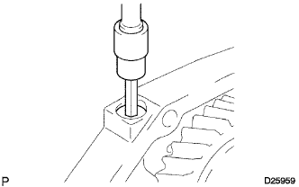
Using hexagon wrench, install the shift detent ball spring seat No. 1 to the intermediate plate.
- Torque:
- 18.5 N*m { 189 kgf*cm, 14 ft.*lbf }
-
-
INSTALL TRANSMISSION MAGNET
-
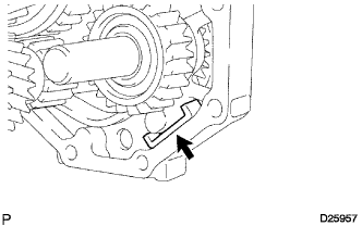
Clean the transmission magnet and install it to the intermediate plate.
-
-
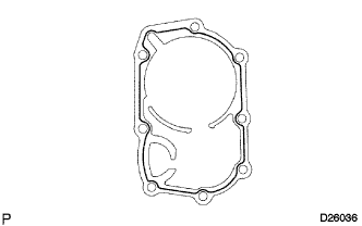
INSTALL MANUAL TRANSMISSION POWER TAKE-OFF COVER
-
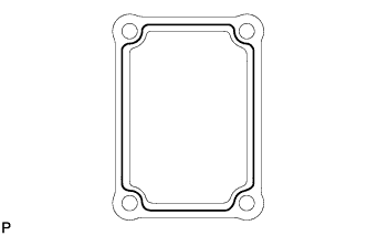
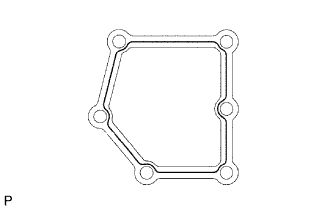
Apply seal packing to the power take-off cove as shown.
Seal packing Toyota Genuine Seal Packing 1281, Three Bond 1281 or equivalent -
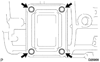
Install the transmission power take-off cover with the 4 bolts.
- Torque:
- 15 N*m { 153 kgf*cm, 11 ft.*lbf }
-
-
INSTALL MANUAL TRANSMISSION CASE
-
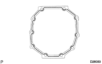
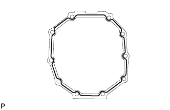
Apply seal packing to the transmission case as shown.
Seal packing Toyota Genuine Seal Packing 1281, Three Bond 1281 or equivalent -
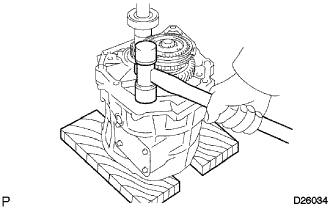
Using a plastic hammer, pat the transmission case to attach to the intermediate plate.
-
-
INSTALL COUNTER GEAR FRONT BEARING SNAP RING NO.1
-
Using a snap ring expander, install the counter gear front bearing snap ring No. 1 to the transmission case.
-
-
INSTALL FRONT BEARING SHAFT SNAP RING
-
Using a snap ring expander, install the front bearing shaft snap ring to the transmission case.
-
-
INSTALL TRANSMISSION FRONT BEARING RETAINER OIL SEAL
-
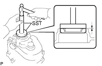
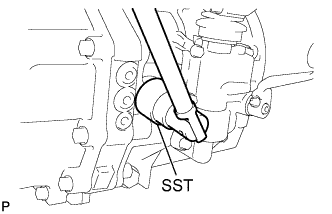
Using SST and a hammer, install a new transmission front bearing retainer oil seal to the transmission front bearing retainer.
- SST
- 09950-60010 ( 09951-00300, 09951-00520, 09952-06010 )
- 09950-70010 ( 09951-07100 )
Standard clearance 11.2 to 12.2 mm (0.4409 to 0.4803 in.) -
Apply MP grease thinly to the oil seal lip.
-
-
INSTALL BEARING RETAINER FRONT (MTM)
-
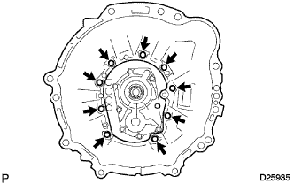
Apply seal packing to the transmission front baring retainer as shown.
Seal packing Toyota Genuine Seal Packing 1281, Three Bond 1281 or equivalent -
Apply sealant to the 8 bolts threads.
Sealant Toyota Genuine Adhesive 1344, Three Bond 1344 or equivalent -
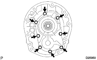
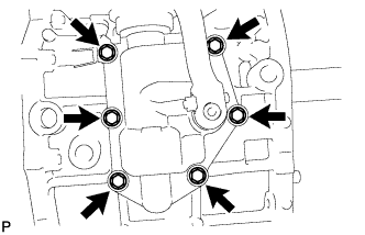
Install the transmission front bearing retainer to the transmission case with the 8 bolts.
- Torque:
- 16.5 N*m { 168 kgf*cm, 12 ft.*lbf }
-
Check that the input shaft and the output shaft rotate smoothly.
-
-
INSTALL MANUAL TRANSMISSION EXTENSION HOUSING OIL SEAL
-
Using SST and a hammer, install a new transmission extension housing oil seal to the transmission extension housing.
- SST
- 09950-60010 ( 09951-00370, 09951-00640, 09952-06010 )
- 09950-70010 ( 09951-07100 )
Drive in depth -0.5 to 0.5 mm (-0.0197 to 0.0197 in.) -
Apply MP grease thinly to the lip of the oil seal.
-
-
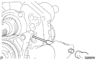
INSTALL EXTENSION HOUSING OIL RECEIVER PIPE NO.2
-
Install the extension housing oil seal receiver pipe No. 2 to the transmission extension housing.
- Torque:
- 11 N*m { 112 kgf*cm, 8 ft.*lbf }
-
-
INSTALL EXTENSION HOUSING OIL RECEIVER PIPE NO.1
-
Install the extension housing oil receiver pipe No. 1 to the transmission extension housing.
-
-
INSTALL EXTENSION (MTM) HOUSING SUB-ASSEMBLY
-
Apply seal packing to the transmission extension housing as shown.
Seal packing Toyota Genuine Seal Packing 1281, Three Bond 1281 or equivalent -
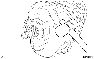
Using a plastic hammer, install the transmission extension housing to the transmission case.
-
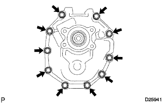
Install the 10 bolts.
- Torque:
- 37 N*m { 377 kgf*cm, 27 ft.*lbf }
-
-
INSTALL SHIFT LEVER SHAFT HOUSING ASSEMBLY
-
Apply seal packing to the shift lever shaft housing as shown.
Seal packing Toyota Genuine Seal Packing 1281, Three Bond 1281 or equivalent -
Install the shift lever shaft housing assembly to the transmission case with the 6 bolts.
- Torque:
- 16.5 N*m { 168 kgf*cm, 12 ft.*lbf }
-
-
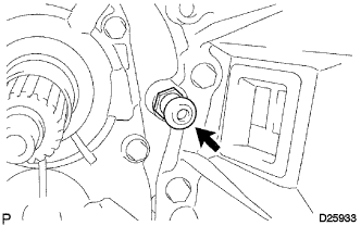
INSTALL BACK-UP LAMP SWITCH ASSEMBLY
-
Using SST, install the back-up lamp switch assembly and gasket to the transmission case.
- SST
- 09817-16011
- Torque:
- 44 N*m { 449 kgf*cm, 32 ft.*lbf }
-
-
INSTALL SPEEDOMETER DRIVEN (MTM) GEAR SUB-ASSEMBLY
-
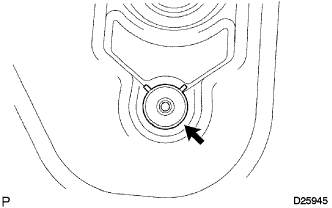
Install the speedometer driven gear to the transmission extension housing with the bolt.
- Torque:
- 11 N*m { 112 kgf*cm, 8 ft.*lbf }
-
-
INSTALL CLUTCH HOUSING
-
Install the clutch housing to the transmission case with the 9 bolts.
- Torque:
- 36 N*m { 367 kgf*cm, 27 ft.*lbf }
-
-
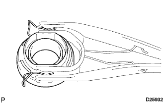
INSTALL CLUTCH RELEASE FORK BOOT
-
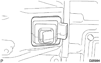
Install the clutch release fork boot to the clutch housing.
-
-
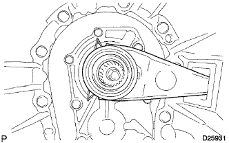
INSTALL RELEASE FORK SUPPORT
-
Install the clutch release fork support to the clutch housing.
- Torque:
- 36.8 N*m { 375 kgf*cm, 27 ft.*lbf }
-
-
INSTALL CLUTCH RELEASE BEARING ASSEMBLY
-
Apply clutch release hub grease to the clutch release bearing and install it to the clutch release fork.
-
-
INSTALL CLUTCH RELEASE FORK SUB-ASSEMBLY
-
Install the clutch release fork.
-
Apply clutch spline grease to the spline of the input shaft.
-
-
INSTALL DRAIN (MTM) PLUG SUB-ASSEMBLY
-
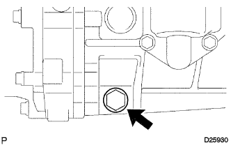
Install the transmission drain plug to the transmission case through a new gasket.
- Torque:
- 37 N*m { 377 kgf*cm, 27 ft.*lbf }
-
-
INSTALL MANUAL TRANSMISSION FILLER PLUG
-
Install the transmission filler plug to the transmission case through a new gasket.
- Torque:
- 37 N*m { 377 kgf*cm, 27 ft.*lbf }
-