MANUAL TRANSMISSION UNIT INSPECTION

-
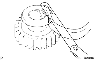
INSPECT COUNTER SHAFT 5TH GEAR THRUST CLEARANCE
-
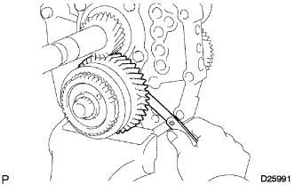
Using a feeler gauge, measure the counter shaft 5th gear thrust clearance.
Standard clearance 0.10 to 0.35 mm (0.00394 to 0.0137 in.) If the clearance is not as specified, replace the counter shaft 5th gear with a new one.
-
-
INSPECT COUNTER SHAFT 5TH GEAR RADIAL CLEARANCE
-
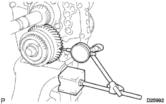
Using a dial indicator, measure the radial clearance of the counter shaft 5th gear.
Standard clearance 0.015 to 0.068 mm (0.000591 to 0.00267 in.) If the clearance is not as specified, replace the counter shaft 5th gear with a new one.
-
-
INSPECT OUTER NO. 3 SYNCHRONIZER RING (for Lever Type Synchronizer Ring)
-
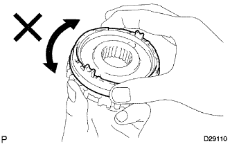
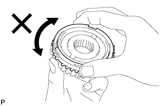
Apply gear oil to the cone part of the No. 5 gear spline piece, and check that it does not turn in either direction while pushing the outer No. 3 synchronizer ring against the No. 5 gear spline piece.
If it can turn, replace the outer No. 3 synchronizer ring with a new one.
-
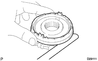
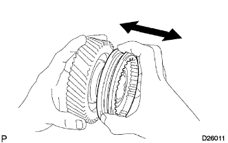
Measure the clearance between the outer No. 3 synchronizer ring and No. 5 gear spline piece while pushing the outer No. 3 synchronizer ring against the cone part of the No. 5 gear spline piece.
Standard clearance 0.68 to 1.32 mm (0.0268 to 0.0519 in.) If the clearance is not as specified, replace the outer No. 3 synchronizer ring with a new one.
-
-
INSPECT NO. 3 SYNCHRONIZER RING (for Single Type Synchronizer Ring)
-
Apply gear oil to the cone part of the No. 5 gear spline piece, and check that it does not turn in either direction while pushing the No. 3 synchronizer ring against the No. 5 gear spline piece.
If it can turn, replace the No. 3 synchronizer ring with a new one.
-
Measure the clearance between the No. 3 synchronizer ring and No. 5 gear spline piece while pushing the No. 3 synchronizer ring against the cone part of the No. 5 gear spline piece.
Standard clearance 0.85 to 1.55 mm (0.0335 to 0.0610 in.) If the clearance is not as specified, replace the No. 3 synchronizer ring with a new one.
-
-
INSPECT NO. 3 TRANSMISSION HUB SLEEVE
-
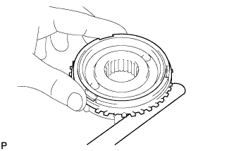
Check that the counter shaft 5th gear and No. 3 transmission hub sleeve slide smoothly against each other.
-
Check the tip of the spline gear of the No. 3 transmission hub sleeve for wear.
If there are any defects, replace the No. 3 transmission hub sleeve.
-
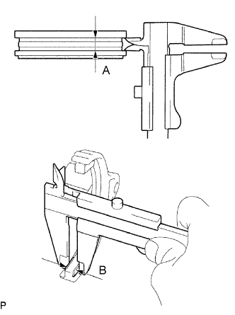
Using a vernier caliper, measure the width of the No. 3 transmission hub sleeve groove and the thickness of the claw part of the No. 3 gear shift fork, and calculate the clearance.
Standard clearance (A - B) 0.24 to 0.84 mm (0.00945 to 0.0331 in.) If the clearance is not within the specified values, replace the No. 3 transmission hub sleeve and No. 3 gear shift fork with new ones.
-
-
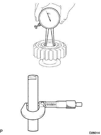
INSPECT COUNTER SHAFT 5TH GEAR
-
Using a cylinder gauge, measure the inner diameter of the counter shaft 5th gear.
Standard diameter 38.015 to 38.040 mm (1.4967 to 1.4976 in.) Maximum diameter 38.040 mm (1.4976 in.) If the inner diameter is greater than the maximum, replace the counter shaft 5th gear with a new one.
-
-
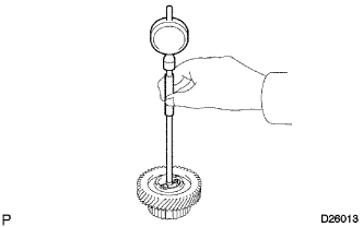
INSPECT REVERSE IDLER GEAR SUB-ASSEMBLY
-
Using a caliper gauge, measure the inner diameter of the reverse idler gear sub-assembly.
Standard diameter 24.040 to 24.061 mm (0.9465 to 0.9472 in.) Maximum diameter 24.061 mm (0.9472 in.) If the inner diameter is greater than the maximum, replace the reverse idler gear sub-assembly with a new one.
-
Using a micrometer, measure the outer diameter of the sliding part of the reverse idler gear sub-assembly on the reverse idler gear shaft.
Standard diameter 23.979 to 24.000 mm (0.9441 to 0.9448 in.) Minimum diameter 23.979 mm (0.9441 in.) If the diameter is less than the minimum, replace the reverse idler gear shaft with a new one.
-
Subtract the reverse idler gear shaft outer diameter from the reverse idler gear sub-assembly inner diameter to calculate the clearance.
Standard clearance 0.040 to 0.082 mm (0.00158 to 0.00322 in.) If the clearance is not as specified, replace the reverse idler gear sub-assembly and reverse idler gear shaft.
-
Using a feeler gauge, measure the thrust clearance of the shoe part between the reverse idler gear sub-assembly and reverse shift arm.
Standard clearance 0.05 to 0.35 mm (0.00197 to 0.0137 in.) If the clearance is outside the specification, replace the reverse idler gear sub-assembly and reverse shift arm with new ones.
-
-
INSPECT REVERSE IDLER GEAR RADIAL CLEARANCE
-
Install the reverse idler gear sub-assembly to the reverse idler gear shaft, and clamp it in a vise.
-
Using a dial indicator, measure the radial clearance.
Standard clearance 0.040 to 0.082 mm (0.00158 to 0.00322 in.) If the clearance is not as specified, replace the reverse idler gear sub-assembly with a new one.
-