MANUAL TRANSMISSION UNIT DISASSEMBLY

-
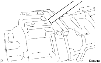
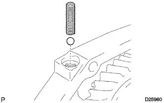
REMOVE MANUAL TRANSMISSION FILLER PLUG
-
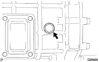
Remove the manual transmission filler plug and gasket from the manual transmission case.
-
-
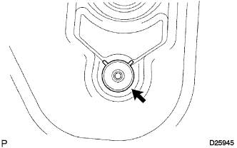
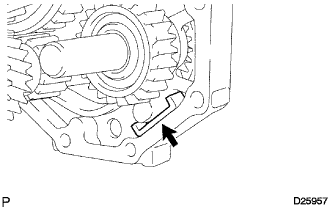
REMOVE DRAIN PLUG SUB-ASSEMBLY
-
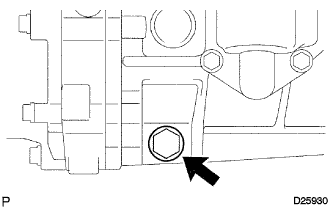
Remove the drain plug sub-assembly and gasket from the manual transmission case.
-
-
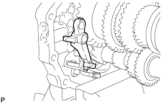
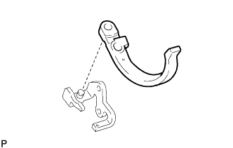
REMOVE CLUTCH RELEASE FORK SUB-ASSEMBLY
-
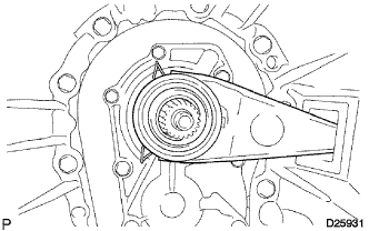
Remove the clutch release fork sub-assembly and clutch release bearing assembly from the clutch housing.
-
-
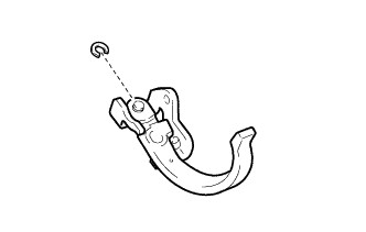
REMOVE CLUTCH RELEASE BEARING ASSEMBLY
-
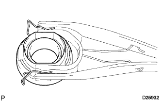
Remove the release bearing hub clip and clutch release bearing assembly from the clutch release fork sub-assembly.
-
-
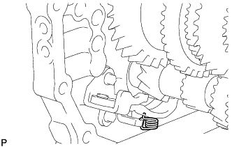
REMOVE RELEASE FORK SUPPORT
-
Remove the release fork support from the clutch housing.
-
-
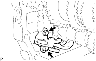
REMOVE CLUTCH RELEASE FORK BOOT
-
Remove the clutch release fork boot from the clutch housing.
-
-
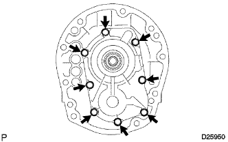
REMOVE CLUTCH HOUSING
-
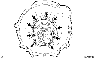
Remove the 9 bolts.
-
Using a plastic hammer, remove the clutch housing from the manual transmission case.
-
-
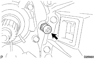
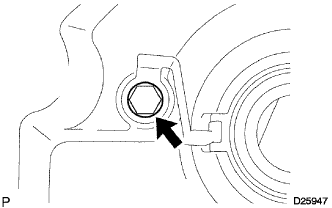
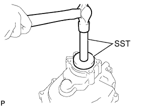
REMOVE BACK-UP LIGHT SWITCH ASSEMBLY
-
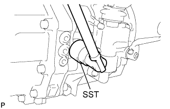
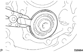
Using SST, remove the back-up light switch assembly and gasket from the manual transmission case.
- SST
- 09817-16011
-
-
REMOVE SPEEDOMETER DRIVEN GEAR SUB-ASSEMBLY
-
Remove the bolt and speedometer driven gear sub-assembly from the extension housing sub-assembly.
-
Remove the O-ring from the speedometer driven gear sub-assembly.
-
-
REMOVE SHIFT LEVER SHAFT HOUSING ASSEMBLY
-
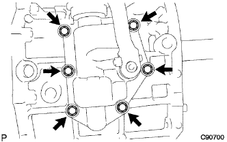
Remove the 6 bolts.
-
Using a plastic hammer, remove the shift lever shaft housing assembly.
-
-
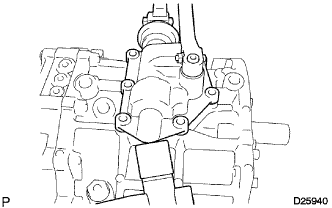
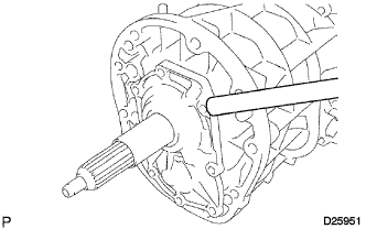
REMOVE EXTENSION HOUSING SUB-ASSEMBLY
-
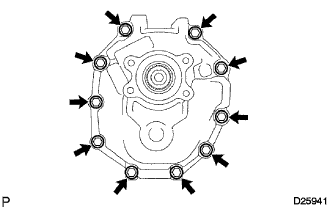
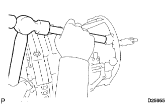
Remove the 10 bolts.
-
Using a brass bar and a hammer, remove the extension housing sub-assembly.
-
-
REMOVE NO. 1 EXTENSION HOUSING OIL RECEIVER PIPE
-
Remove the No. 1 extension housing oil receiver pipe from the extension housing sub-assembly.
-
-
REMOVE NO. 2 EXTENSION HOUSING OIL RECEIVER PIPE
-
Remove the bolt and No. 2 extension housing oil receiver pipe from the extension housing sub-assembly.
-
-
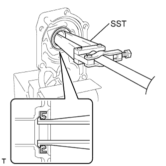
REMOVE MANUAL TRANSMISSION EXTENSION HOUSING OIL SEAL
-
Using SST, remove the manual transmission extension housing oil seal from the extension housing sub-assembly.
- SST
- 09950-60010 ( 09951-00640 )
- 09950-70010 ( 09951-07100 )
-
-
REMOVE FRONT BEARING RETAINER
-
Remove the 8 bolts.
-
Using a brass bar and a hammer, remove the front bearing retainer from the manual transmission case.
-
-
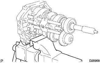
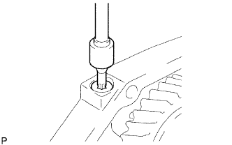
REMOVE FRONT TRANSMISSION BEARING RETAINER OIL SEAL
-
Fix the front bearing retainer in a vise between aluminum plates.
Note
Do not overtighten the vise.
-
Using SST, remove the front transmission bearing retainer oil seal.
- SST
- 09308-00010
-
-
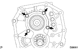
REMOVE FRONT BEARING SHAFT SNAP RING
-
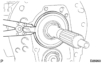
Using a snap ring expander, remove the front bearing shaft snap ring from the front input shaft bearing.
Note
Use a piece of cloth to prevent the front bearing shaft snap ring from flying off.
-
-
REMOVE FRONT NO. 1 COUNTER GEAR BEARING SNAP RING
-
Using a snap ring expander, remove the front No. 1 counter gear bearing snap ring from the front counter gear shaft bearing.
Note
Use a piece of cloth to prevent the front No. 1 counter gear bearing snap ring from flying off.
-
-
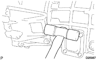
REMOVE MANUAL TRANSMISSION CASE
-
Using a brass bar and a hammer, remove the manual transmission case from the intermediate plate.
-
-
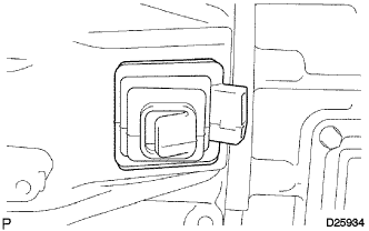
REMOVE MANUAL TRANSMISSION POWER TAKE-OFF COVER
-
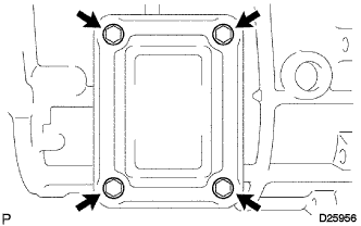
Remove the 4 bolts.
-
Using a brass bar and a hammer, remove the manual transmission power take-off cover from the manual transmission case.
-
-
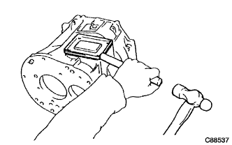
REMOVE TRANSMISSION MAGNET
-
Remove the transmission magnet from the intermediate plate.
-
-
FIX INTERMEDIATE PLATE
-
Fix the intermediate plate in a vise between aluminum plates.
Note
Do not overtighten the vise.
-
-
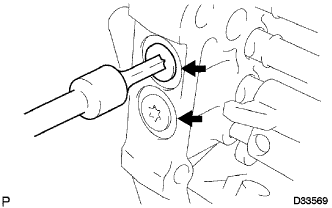
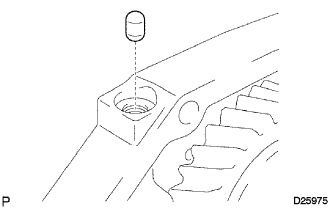
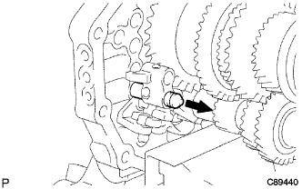
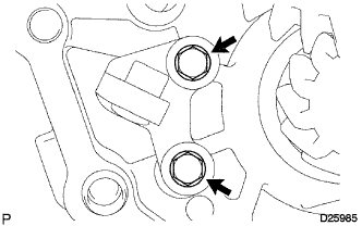
REMOVE NO. 1 SHIFT DETENT BALL SPRING SEAT
-
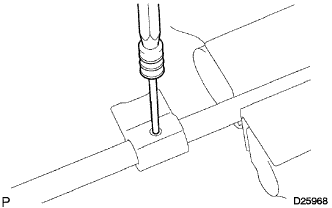
Using a T40 "TORX" socket wrench, remove the No. 1 shift detent ball spring seat from the intermediate plate.
-
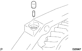
Using a magnet hand, remove the shift detent ball low side spring and shift detent ball from the intermediate plate.
-
Using a T40 "TORX" socket wrench, remove the 2 No. 1 shift detent ball spring seats from the intermediate plate.
-
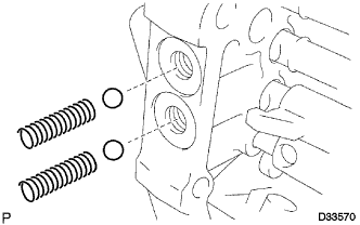
Using a magnet hand, remove the 2 shift detent ball low side springs and 2 shift detent balls from the intermediate plate.
-
-
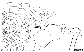
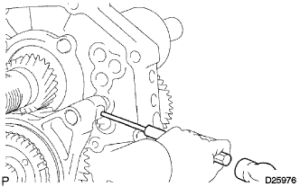
REMOVE SHIFT FORK SHAFT STOPPER
-
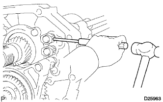
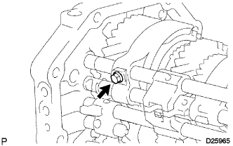
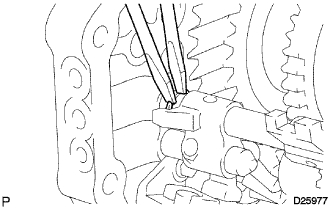
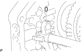
Using a 5 mm pin punch and a hammer, remove the shift fork shaft stopper slotted pin from the No. 1 gear shift fork shaft.
-
Remove the shift fork shaft stopper from the No. 1 gear shift fork shaft.
-
-
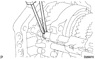
REMOVE NO. 1 GEAR SHIFT FORK SHAFT
-
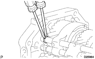
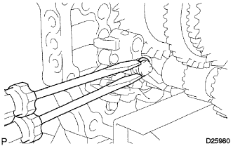
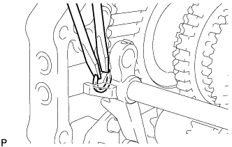
Using 2 screwdrivers and a hammer, remove the snap ring from the No. 1 gear shift fork shaft.
Note
Use a piece of cloth to prevent the snap ring from flying off.
-
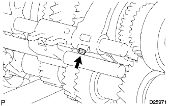
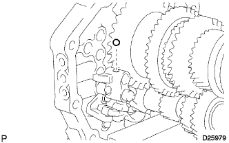
Remove the bolt from the No. 1 gear shift fork.
-
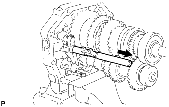
Remove the No. 1 gear shift fork shaft from the intermediate plate.
-
Using a magnet hand, remove the No. 1 shift interlock roller and shift interlock pin from the intermediate plate.
-
-
REMOVE NO. 1 GEAR SHIFT HEAD (w/ No. 4 Gear Shift Fork Shaft)
-
Using a 5 mm pin punch and a hammer, remove the shift head slotted pin from the No. 1 gear shift head.
-
Remove the No. 1 gear shift head from the No. 1 gear shift fork shaft.
-
-
REMOVE SHIFT FORK SHAFT STOPPER
-
Using a 5 mm pin punch and a hammer, remove the shift fork shaft stopper slotted pin from the No. 2 gear shift fork shaft.
-
Remove the shift fork shaft stopper from the No. 2 gear shift fork shaft.
-
-
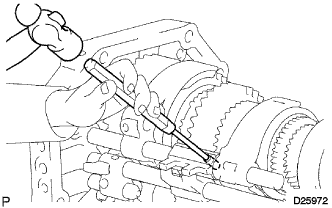
REMOVE NO. 2 GEAR SHIFT FORK SHAFT
-
Using 2 screwdrivers and a hammer, remove the snap ring from the No. 2 gear shift fork shaft.
Note
Use a piece of cloth to prevent the snap ring from flying off.
-
Remove the bolt from the No. 2 gear shift fork.
-
Using a 5 mm pin punch and a hammer, remove the shift head slotted pin from the No. 2 gear shift fork shaft.
-
Remove the No. 2 gear shift fork shaft and No. 2 gear shift head.
-
Remove the No. 1 gear shift fork and No. 2 gear shift fork from the output shaft.
-
Using a magnet hand, remove the No. 1 shift interlock roller from the intermediate plate.
-
-
REMOVE NO. 3 GEAR SHIFT FORK SHAFT (w/ No. 4 Gear Shift Fork Shaft)
-
Using a 5 mm pin punch and a hammer, remove the shift fork slotted pin from the No. 3 gear shift fork shaft.
-
Using 2 screwdrivers and a hammer, remove the snap ring from the No. 3 gear shift fork shaft.
Note
Use a piece of cloth to prevent the snap ring from flying off.
-
Remove the No. 3 gear shift fork shaft and No. 3 gear shift fork.
-
Using a magnet hand, remove the No. 1 shift interlock roller from the intermediate plate.
-
Using a magnet hand, remove the reverse shift fork ball from the reverse shift fork.
-
-
REMOVE NO. 1 GEAR SHIFT HEAD (w/ No. 4 Gear Shift Fork Shaft)
-
Using a 5 mm pin punch and a hammer, remove the shift head slotted pin from the No. 1 gear shift head.
-
Remove the No. 1 gear shift head from the No. 3 gear shift fork shaft.
-
-
REMOVE NO. 4 GEAR SHIFT FORK SHAFT (w/ No. 4 Gear Shift Fork Shaft)
-
Using 2 screwdrivers and a hammer, remove the shift fork shaft snap ring from the No. 4 gear shift fork shaft.
Note
Use a piece of cloth to prevent the shift fork shaft snap ring from flying off.
-
Remove the No. 4 gear shift fork shaft from the intermediate plate.
Note
Cover the hole with a piece of cloth to prevent the reverse shift fork ball from popping out.
-
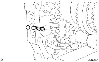
Using a magnet hand, remove the reverse shift fork ball and compression spring from the reverse shift fork.
-
-
REMOVE REVERSE SHIFT FORK (w/ No. 4 Gear Shift Fork Shaft)
-
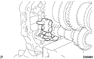
Remove the reverse shift fork together with the reverse shift arm from the intermediate plate.
-
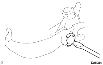
Using a screwdriver, remove the reverse shift arm end shaft ring and reverse shift fork from the reverse shift arm.
Note
Use a piece of cloth to prevent the reverse shift arm end shaft ring from flying off.
-
-
REMOVE REVERSE SHIFT ARM BRACKET (w/ No. 4 Gear Shift Fork Shaft)
-
Remove the 2 bolts and reverse shift arm bracket from the intermediate plate.
-
-
REMOVE NO. 3 GEAR SHIFT FORK SHAFT (w/o No. 4 Gear Shift Fork Shaft)
-
Using a 5 mm pin punch and a hammer, remove the shift fork slotted pin from the No. 3 gear shift fork.
-
Using 2 screwdrivers and a hammer, remove the snap ring from the No. 3 gear shift fork shaft.
Note
Use a piece of cloth to prevent the snap ring from flying off.
-
Using a magnet hand, remove the straight pin from the reverse shift fork.
-
Remove the No. 3 gear shift fork and No. 3 gear shift fork shaft from the intermediate plate.
-
-
REMOVE REVERSE SHIFT FORK (w/o No. 4 Gear Shift Fork Shaft)
-
Remove the reverse shift fork from the reverse shift arm.
-
-
REMOVE REVERSE SHIFT ARM BRACKET (w/o No. 4 Gear Shift Fork Shaft)
-
Remove the torsion spring from the reverse shift arm bracket.
-
Remove the 2 bolts and reverse shift arm bracket from the intermediate plate.
-
Using a screwdriver, pry out the snap ring from the reverse shift arm bracket.
Note
Use a piece of cloth to prevent the snap ring from flying off.
-
Remove the reverse shift arm from the reverse shift arm bracket.
-
-
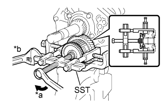
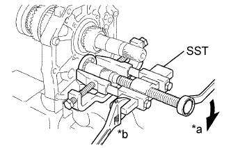
REMOVE REAR OUTPUT SHAFT BEARING
-
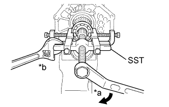
Text in Illustration *a Turn *b Hold Using SST, remove the rear output shaft bearing from the output shaft assembly.
- SST
- 09950-40011 ( 09951-04010, 09952-04010, 09953-04020, 09954-04010, 09955-04051, 09957-04010, 09958-04011 )
Note
Apply grease to the threads and tip of the SST center bolt before use.
-
-
REMOVE SPEEDOMETER DRIVE GEAR
-
Remove the speedometer drive gear from the output shaft assembly.
-
-
REMOVE SPEEDOMETER DRIVE GEAR KEY OR BALL
-
Remove the speedometer drive gear key or ball from the output shaft assembly.
-
-
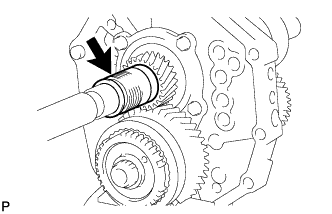
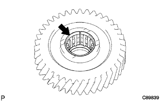
INSPECT COUNTER SHAFT 5TH GEAR THRUST CLEARANCE
-
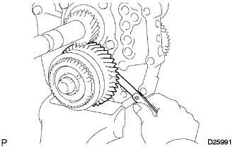
Using a feeler gauge, measure the counter shaft 5th gear thrust clearance.
Standard clearance 0.10 to 0.35 mm (0.00394 to 0.0137 in.) If the clearance is not as specified, replace the counter shaft 5th gear with a new one.
-
-
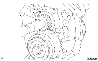
INSPECT COUNTER SHAFT 5TH GEAR RADIAL CLEARANCE
-
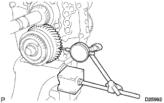
Using a dial indicator, measure the radial clearance of the counter shaft 5th gear.
Standard clearance 0.015 to 0.068 mm (0.000591 to 0.00267 in.) If the clearance is not as specified, replace the counter shaft 5th gear with a new one.
-
-
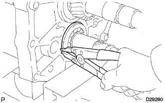
REMOVE REAR COUNTER GEAR SHAFT SNAP RING
-
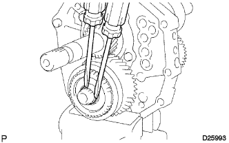
Using 2 screwdrivers and a hammer, remove the rear counter gear shaft snap ring from the counter gear assembly.
Note
Use a piece of cloth to prevent the rear counter gear shaft snap ring from flying off.
-
-
REMOVE NO. 5 GEAR SPLINE PIECE (for Single Type Synchronizer Ring)
-
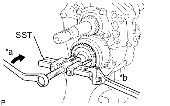
Text in Illustration *a Turn *b Hold Using SST, remove the No. 5 gear spline piece from the counter gear assembly.
- SST
- 09950-50013 ( 09951-05010, 09952-05010, 09952-06010, 09953-05020, 09954-05021, 09957-04010 )
Note
Apply grease to the threads and tip of the SST center bolt before use.
-
-
REMOVE NO. 3 SYNCHRONIZER RING (for Single Type Synchronizer Ring)
-
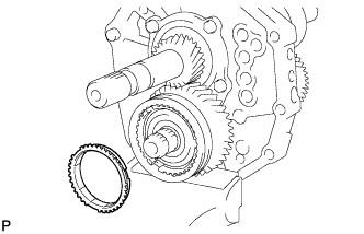
Remove the No. 3 synchronizer ring from the counter gear assembly.
-
-
REMOVE COUNTER SHAFT 5TH GEAR (for Single Type Synchronizer Ring)
-
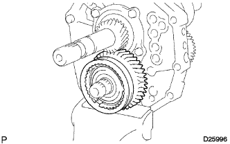
Remove the counter shaft 5th gear and No. 3 transmission hub sleeve from the counter gear assembly.
-
-
REMOVE NO. 3 SYNCHROMESH SHIFTING KEY (for Single Type Synchronizer Ring)
-
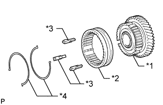
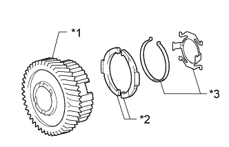
Text in Illustration *1 Counter Shaft 5th Gear *2 No. 3 Transmission Hub Sleeve *3 No. 3 Synchromesh Shifting Key *4 No. 3 Synchromesh Shifting Key Spring Remove the No. 3 transmission hub sleeve, 3 No. 3 synchromesh shifting keys and 2 No. 3 synchromesh shifting key springs from the counter shaft 5th gear.
-
-
REMOVE NO. 3 TRANSMISSION HUB SLEEVE (for Lever Type Synchronizer Ring)
-
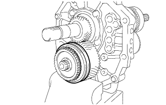
Remove the No. 3 transmission hub sleeve from the counter shaft 5th gear.
-
-
REMOVE COUNTER SHAFT 5TH GEAR (for Lever Type Synchronizer Ring)
-
Text in Illustration *a Turn *b Hold Using SST, remove the counter shaft 5th gear together with the outer No. 3 synchronizer ring and No. 5 gear spline piece from the counter gear assembly.
- SST
- 09950-40011 ( 09951-00040, 09951-04020, 09952-04010, 09953-04020, 09954-04010, 09955-03021, 09957-04010, 09958-04011 )
Note
Apply grease to the threads and tip of the SST center bolt before use.
-
-
REMOVE NO. 5 GEAR SPLINE PIECE (for Lever Type Synchronizer Ring)
-
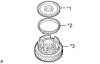
Text in Illustration *1 No. 5 Gear Spline Piece *2 Outer No. 3 Synchronizer Ring *3 Counter Shaft 5th Gear Remove the No. 5 gear spline piece from the counter shaft 5th gear.
-
-
REMOVE OUTER NO. 3 SYNCHRONIZER RING (for Lever Type Synchronizer Ring)
-
Remove the outer No. 3 synchronizer ring from the counter shaft 5th gear.
-
-
REMOVE NO. 3 SYNCHROMESH SHIFTING KEY (for 1-piece Type)
-

Using a snap ring expander, remove the shaft snap ring.
Note
Use a piece of cloth to prevent the shaft snap ring from flying off.
-
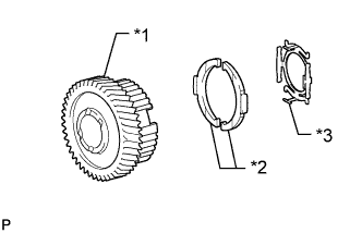
Text in Illustration *1 Counter Shaft 5th Gear *2 No. 3 Synchromesh Shifting Key *3 No. 3 Synchromesh Shifting Key Spring Remove the 2 No. 3 synchromesh shifting keys and No. 3 synchromesh shifting key spring from the counter shaft 5th gear.
-
-
REMOVE NO. 3 SYNCHROMESH SHIFTING KEY (for 2-piece Type)
-
Using a snap ring expander, remove the shaft snap ring.
Note
Use a piece of cloth to prevent the shaft snap ring from flying off.
-
Text in Illustration *1 Counter Shaft 5th Gear *2 No. 3 Synchromesh Shifting Key *3 No. 3 Synchromesh Shifting Key Spring Remove the 2 No. 3 synchromesh shifting keys and 2 No. 3 synchromesh shifting key springs from the counter shaft 5th gear.
-
-
REMOVE COUNTER 5TH GEAR BEARING
-
Remove the counter 5th gear bearing from the counter shaft 5th gear.
-
-
REMOVE 5TH GEAR THRUST WASHER
-
Remove the 5th gear thrust washer from the counter gear assembly.
-
-
REMOVE 5TH GEAR THRUST WASHER PIN
-
Remove the 5th gear thrust washer pin from the counter gear assembly.
-
-
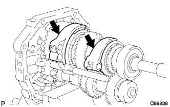
REMOVE REAR OUTPUT SHAFT BEARING RETAINER
-
Remove the 4 bolts and rear output shaft bearing retainer from the intermediate plate.
-
-
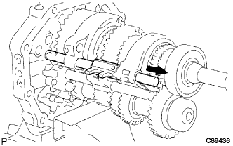
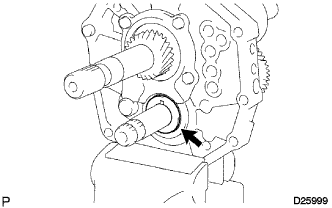
REMOVE REVERSE IDLER GEAR SUB-ASSEMBLY
-
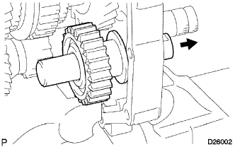
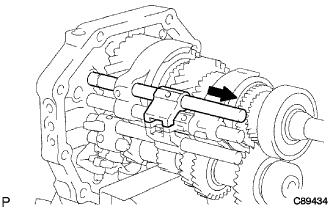
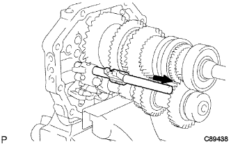
Pull out the reverse idler gear shaft to the rear side and remove the reverse idler gear sub-assembly from the intermediate plate.
-
-
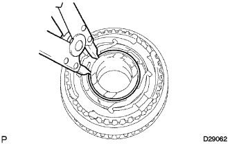
REMOVE CENTER COUNTER SHAFT BEARING
-
Using a snap ring expander, remove the snap ring from the center counter shaft bearing.
Note
Use a piece of cloth to prevent the snap ring from flying off.
-
Text in Illustration *a Turn *b Hold Using SST, remove the center counter shaft bearing from the counter gear assembly.
- SST
- 09950-40011 ( 09951-04010, 09952-04010, 09953-04020, 09954-04010, 09955-04011, 09957-04010, 09958-04011 )
Note
Apply grease to the threads and tip of the SST center bolt before use.
Tech Tips
Remove the center counter shaft bearing while tapping the tip of the counter gear assembly with a plastic hammer so that the counter gear assembly does not hit the side wall of the output shaft gear by being pushed forward.
-
-
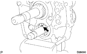
REMOVE COUNTER GEAR ASSEMBLY
-
Remove the counter gear assembly from the intermediate plate.
Note
Do not drop the counter gear assembly.
-
-
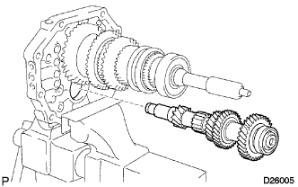
REMOVE INPUT SHAFT ASSEMBLY
-
Remove the input shaft assembly and No. 2 synchronizer ring from the output shaft assembly.
Note
Do not drop the input shaft assembly and No. 2 synchronizer ring.
-
-
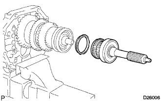
REMOVE OUTPUT SHAFT BEARING SHAFT SNAP RING
-
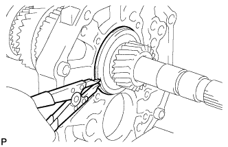
Using a snap ring expander, remove the output shaft bearing shaft snap ring from the output shaft assembly.
Note
Use a piece of cloth to prevent the output shaft bearing shaft snap ring from flying off.
-
-
REMOVE OUTPUT SHAFT ASSEMBLY
-
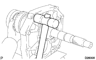
Using a plastic hammer, remove the output shaft assembly by tapping the intermediate plate.
-