MANUAL TRANSMISSION EXTENSION HOUSING OIL SEAL REPLACEMENT

-
REMOVE ENGINE UNDER COVER SUB-ASSEMBLY NO.2
-
DRAIN MANUAL TRANSMISSION OIL
-
REMOVE PROPELLER SHAFT ASSEMBLY REAR (2 JOINT TYPE PROPELLER SHAFT)
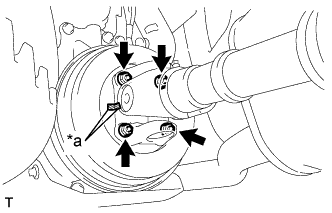
Text in Illustration *a Matchmark
-
Place matchmarks on the propeller shaft flange and parking brake drum or flange.
-
Remove the 4 nuts, 4 bolts and washers.
-
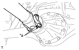
Text in Illustration *a Matchmark Place matchmarks on the propeller shaft flange and differential flange.
-
Remove the 4 nuts, 4 bolts and 4 washers.
-
-
REMOVE INTERMEDIATE SHAFT (3 JOINT TYPE PROPELLER SHAFT)
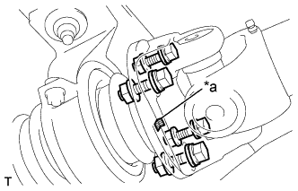
-
Place matchmarks on the propeller shaft flange and intermediate shaft.
Text in Illustration *a Matchmark -
Remove the 4 nuts, bolts and washers.
-
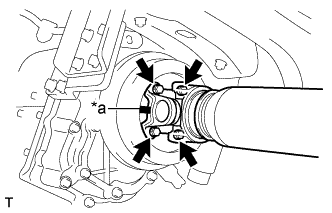
Text in Illustration *a Matchmark Place matchmarks on the propeller shaft and parking brake drum.
-
Remove the 4 nuts and washers.
-
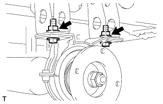
Remove the 2 bolts and 2 nuts.
-
-
REMOVE PROPELLER SHAFT ASSEMBLY REAR (3 JOINT TYPE PROPELLER SHAFT)
Text in Illustration *a Matchmark
-
Place matchmarks on the propeller shaft flange and differential.
-
Remove the 4 nuts, 4 bolts and washers.
-
-
REMOVE PARKING BRAKE DRUM SUB-ASSEMBLY
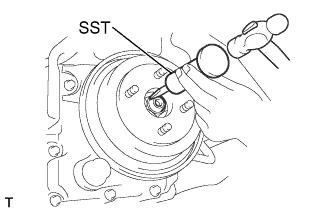
-
Pull the parking brake lever full distance.
-
Using a SST and a hammer, loosen the staked part of the nut.
- SST
- 09930-00010
-
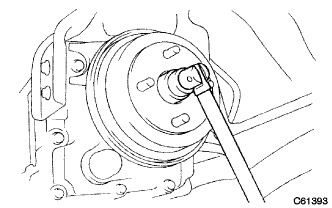
Using socket wrench 32 mm, remove the nut.
-
Remove the drum.
Tech Tips
If the brake drum cannot be removed easily, turn the shoe adjuster clockwise until the drum turns freely.
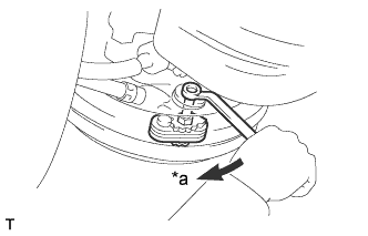
Text in Illustration *a Turn
-
-
SEPARATE PARKING BRAKE PLATE SUB-ASSEMBLY
-
Remove the 4 bolts, separate the parking brake plate sub-assembly from the transmission assembly.
-
-
REMOVE MANUAL TRANSMISSION EXTENSION HOUSING OIL SEAL
-
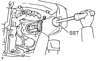
Using SST, remove the oil seal.
- SST
- 09308-00010
-
-
INSTALL MANUAL TRANSMISSION EXTENSION HOUSING OIL SEAL
-
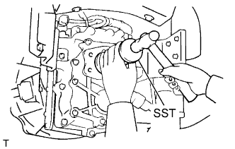
Coat a new oil seal lip with MP grease.
-
Using SST and a hammer, install the oil seal.
- SST
- 09316-60011 ( 09316-00011, 09316-00021 )
-
-
INSTALL PARKING BRAKE PLATE SUB-ASSEMBLY
-
Install the parking brake plate sub-assembly with the 4 bolts.
- Torque:
- 24.5 N*m { 250 kgf*cm, 18 ft.*lbf }
-
-
INSTALL PARKING BRAKE DRUM SUB-ASSEMBLY
-
Install the brake drum, new O-ring and new nut.
-
Using a socket wrench (32mm), tight the nut.
- Torque:
- 127 N*m { 1300 kgf*cm, 94 ft.*lbf }
-
-
ADJUST PARKING BRAKE SHOE CLEARANCE
-
Turn the shoe adjuster counterclockwise until the brake shoes are fully expanded.
-
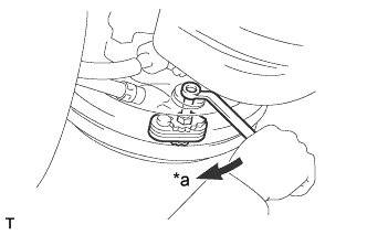
Text in Illustration *a Contracted Turn the shoe adjuster clockwise 1 notch.
-
With the parking brake pulled its full distance, check that the drum is locked.
-
Release the parking brake lever and ensure that the parking brake is not dragging.
Tech Tips
If it is dragging, turn the shoe adjuster clockwise another notch.
-
-
INSTALL PROPELLER SHAFT ASSEMBLY REAR (2 JOINT TYPE PROPELLER SHAFT)
Text in Illustration *a Matchmark
-
Align the matchmarks on the yoke and parking brake down or flange.
-
Install the 4 bolts, 4 nuts and 4 washers.
- Torque:
- Bolt size M 10
- 74 N*m { 755 kgf*cm, 55 ft.*lbf }
- Bolt size M 11
- 88 N*m { 897 kgf*cm, 65 ft.*lbf }
-
Text in Illustration *a Matchmark Align the matchmarks on the yoke and differential flange.
-
Install the 4 bolts, 4 nuts and 4 washers.
- Torque:
- Bolt size M 10
- 74 N*m { 755 kgf*cm, 55 ft.*lbf }
- Bolt size M 11
- 88 N*m { 897 kgf*cm, 65 ft.*lbf }
-
-
INSTALL PROPELLER SHAFT ASSEMBLY REAR (3 JOINT TYPE PROPELLER SHAFT)
Text in Illustration *a Matchmark
-
Align the matchmarks on the propeller shaft flange and differential.
-
Install the 4 bolts, washers and nuts.
- Torque:
- 88 N*m { 897 kgf*cm, 65 ft.*lbf }
-
-
INSTALL INTERMEDIATE SHAFT (3 JOINT TYPE PROPELLER SHAFT)
-
After align the matchmarks of the brake drum and propeller intermediate shaft, install the 4 nuts and washers.
Text in Illustration *a Matchmark - Torque:
- 88 N*m { 897 kgf*cm, 65 ft.*lbf }
-
Fully tighten the 2 nuts.
- Torque:
- 37 N*m { 370 kgf*cm, 27 ft.*lbf }
-
Text in Illustration *a Matchmark Align the matchmarks on the propeller intermediate shaft and propeller shaft assembly.
-
Install the 4 bolts, washers and nuts.
- Torque:
- 88 N*m { 897 kgf*cm, 65 ft.*lbf }
-
-
ADD MANUAL TRANSMISSION OIL
-
Stop the vehicle on the level place.
-
Remove the transmission filler plug and gasket.
-
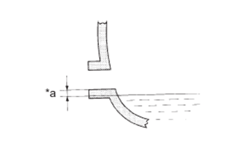
Text in Illustration *a 0 to 5 mm (0 to 0.20 in.) Check that the oil surface is within 5 mm (0.20 in.) from the lowest position of the inner surface of the transmission filler plug opening.
Note
-
Excessively large or small amount of oil may cause troubles.
-
After replacing oil, drive the vehicle and check the oil level.
-
-
Check for oil leakage when the oil level is low.
-
Install the transmission filler plug and a new gasket.
- Torque:
- 37 N*m { 377 kgf*cm, 27 ft.*lbf }
-
-
INSTALL ENGINE UNDER COVER SUB-ASSEMBLY NO.2