CLUTCH UNIT (for 1KD-FTV) INSTALLATION

-
INSTALL INPUT SHAFT BEARING
-
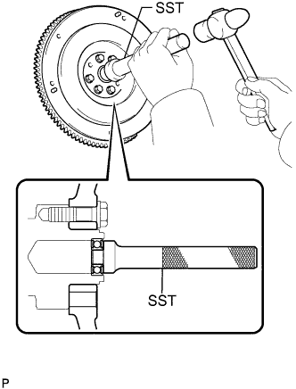
Using SST and a hammer, install a new input shaft bearing.
- SST
- 09304-12012
Tech Tips
After installing the input shaft bearing in the hub, make sure that it rotates smoothly.
-
Install the 2 bolts.
- Torque:
- 178 N*m { 1815 kgf*cm, 131 ft.*lbf }
-
-
INSTALL CLUTCH DISC ASSEMBLY
-
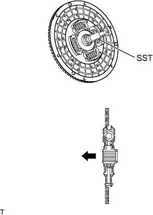
Insert SST into the clutch disc assembly, then insert them into the flywheel sub-assembly.
Text in Illustration 
Flywheel Side - SST
- 09301-00110
Note
Take care not to insert the clutch disc assembly in the wrong direction.
-
-
INSTALL CLUTCH COVER ASSEMBLY
-
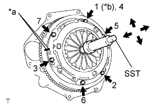
Text in Illustration *a Matchmark *b Temporarily Align the matchmarks on the clutch cover assembly with the one on the flywheel sub-assembly.
-
Following the procedures shown in the illustration, tighten the 6 bolts starting from the bolt located near the knock pin on the top.
- Torque:
- 19 N*m { 195 kgf*cm, 14 ft.*lbf }
Tech Tips
-
Evenly tighten the bolts by following the order shown in the illustration.
-
Tighten the bolts after checking that the disc is in the center by lightly moving SST up and down, left and right.
- SST
- 09301-00110
-
-
INSPECT AND ADJUST CLUTCH COVER ASSEMBLY
-
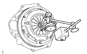
Using a dial indicator with a roller instrument, check the diaphragm spring tip alignment.
Maximum non-alignment 1.3 mm (0.051 in.) -
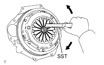
If the alignment is not as specified, adjust the diaphragm spring tip alignment using SST.
- SST
- 09333-00013
-
-
INSTALL RELEASE FORK SUPPORT
-
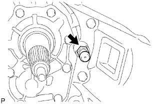
Install the release fork support to the transmission unit.
- Torque:
- 47 N*m { 479 kgf*cm, 35 ft.*lbf }
-
-
INSTALL CLUTCH RELEASE FORK BOOT
-
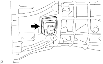
Install the clutch release fork boot to the transmission unit.
-
-
INSTALL CLUTCH RELEASE FORK SUB-ASSEMBLY
-
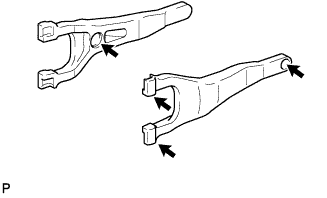
Apply release hub grease to the clutch release fork, clutch release bearing, push rod contact point and the pivot point as shown in the illustration.
Text in Illustration Release Hub Grease Sealant Toyota Genuine Release Hub Grease or equivalent -
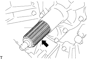
Apply clutch spline grease to the input shaft spline.
Text in Illustration Clutch Spline Grease Sealant Toyota Genuine Clutch Spline Grease or equivalent -
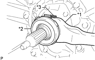
Text in Illustration *1 Clutch Release Fork *2 Clutch Release Bearing *3 Clip Install the clutch release bearing to the clutch release fork with the clip.
-
Install the clutch release fork with the clutch release bearing to the transmission unit.
Note
After installation, move the fork back and forth to check that the clutch release bearing slides smoothly.
-
-
INSTALL MANUAL TRANSMISSION ASSEMBLY
-
for R351: Click here
-
for R451: Click here
-