OUTPUT SHAFT REASSEMBLY

-
INSTALL TRANSMISSION HUB SLEEVE NO.2
-
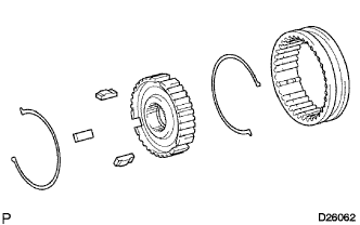
Apply gear oil to the sliding part of the transmission hub sleeve No. 2 and install it to the transmission clutch hub No. 2.
Note
Be sure of the direction of the transmission hub sleeve No. 2 and that of the transmission clutch hub No. 2.
-
Install the 2 synchromesh shifting key springs No. 2 and the 3 synchromesh shifting keys No. 2 to the transmission clutch hub No. 2.
Note
Do not set both opening of the shifting key springs in the opposite position.
-
-
INSTALL 3RD GEAR NEEDLE ROLLER BEARING
-
Apply gear oil to the 3rd gear needle roller bearing and install it to the output shaft.
-
-
INSTALL 3RD GEAR
-
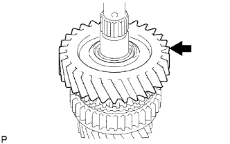
Apply gear oil to the 3rd gear and install it to the output shaft.
-
-
INSTALL SYNCHRONIZER RING NO.2 (FOR THIRD SYNCHRONIZER RING)
-
Apply gear oil to the synchronizer ring No. 2 and install it to the 3rd gear.
-
-
INSTALL TRANSMISSION CLUTCH HUB NO.2
-
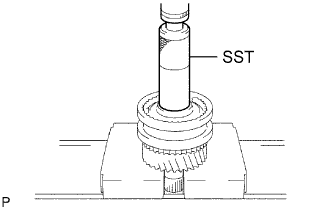
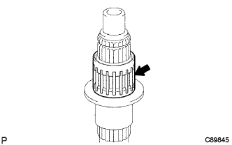
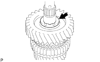
Using SST, install transmission clutch hub No. 2 to the output shaft.
- SST
- 09608-06041
Note
-
Install with aligning the synchronizer ring key No. 2 groove and the shifting key position.
-
3rd gear should rotate lightly.
-
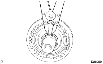
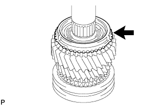
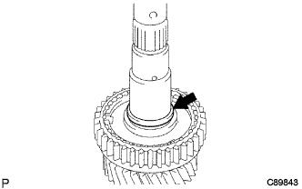
Select the clutch hub shaft snap ring so that the gap between the transmission clutch hub No. 2 and the shaft snap ring No. 2 thrust will be within the specification. Using a brass bar and a hammer, install it to the output shaft.
Standard clearance 0.1 mm (0.0039 in.) or less Mark Thickness mm (in.) A 1.80 to 1.85 (0.0709 to 0.0728) B 1.85 to 1.90 (0.0728 to 0.0748) C 1.90 to 1.95 (0.0748 to 0.0768) D 1.95 to 2.00 (0.0768 to 0.0787) E 2.00 to 2.05 (0.0787 to 0.0807) F 2.05 to 2.10 (0.0807 to 0.0827) G 2.10 to 2.15 (0.0827 to 0.0846) Note
Do not damage the sliding surface of the bearing.
-
-
INSTALL 2ND GEAR NEEDLE ROLLER BEARING
-
Apply gear oil to the 2nd gear needle roller bearing and install it to the output shaft.
-
-
INSTALL 2ND GEAR
-
Apply gear oil to the 2nd gear and install it to the output shaft.
-
-
INSTALL SYNCHRONIZER RING NO.1 (FOR SECOND SYNCHRONIZER RING)
-
Apply gear oil to the synchronizer ring No. 1 and install it to the 2nd gear.
-
-
INSTALL REVERSE GEAR
-
Apply gear oil to the reverse gear and install it to the transmission clutch hub No. 1.
-
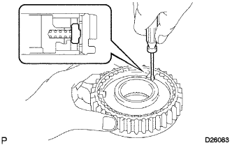
Using a screwdriver, install the 3 synchromesh shifting key springs No. 1 and the 3 synchromesh shifting keys No. 1 to the transmission clutch hub No. 1.
-
-
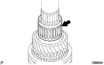
INSTALL TRANSMISSION CLUTCH HUB NO.1
-
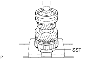
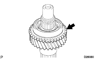
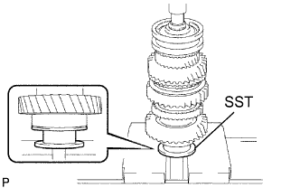
Using SST and a press, install the transmission clutch hub No. 1 to the output shaft.
- SST
- 09316-60011 ( 09316-00041 )
Note
-
Install with checking the synchronizer ring key No. 1 groove and the synchromesh shifting key No. 1 position.
-
1st gear should rotate.
-
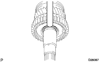
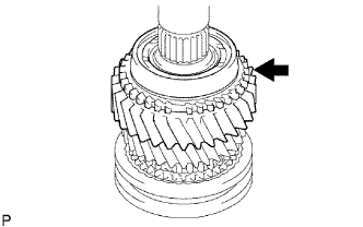
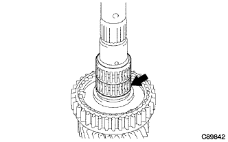
Select the bearing shaft snap ring so that the thrust gap between the transmission clutch hub No. 1 and the bearing shaft snap ring will be within the specification. Using a brass bar and a hammer, install it to the output shaft.
Standard clearance 0.1 mm (0.0039 in.) or less Mark Thickness mm (in.) A 2.30 to 2.35 (0.0906 to 0.0925) B 2.35 to 2.40 (0.0925 to 0.0945) C 2.40 to 2.45 (0.0945 to 0.0965) D 2.45 to 2.50 (0.0965 to 0.0984) E 2.50 to 2.55 (0.0984 to 0.1004) F 2.55 to 2.60 (0.1004 to 0.1024) G 2.60 to 2.65 (0.1024 to 0.1043) Note
Do not damage the sliding surface of the bearing.
-
-
INSTALL 1ST GEAR BEARING SPACER
-
Apply gear oil to the 1st gear bearing spacer, and install it to the output shaft.
-
-
INSTALL 1ST GEAR NEEDLE ROLLER BEARING
-
Apply gear oil to the 1st gear needle roller bearing and install it to the output shaft.
-
-
INSTALL 1ST GEAR THRUST WASHER PIN OR BALL
-
Install the 1st gear thrust washer pin into the output shaft.
-
-
INSTALL SYNCHRONIZER RING NO.1 (FOR FIRST SYNCHRONIZER RING)
-
Apply gear oil to the synchronizer ring No. 1 install it to the 1st gear.
-
-
INSTALL 1ST GEAR
-
Apply gear oil to the 1st gear and install it to the output shaft.
-
-
INSTALL 1ST GEAR THRUST WASHER
-
Apply gear oil to the 1st gear thrust washer and install it to the output shaft.
-
-
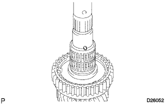
INSTALL OUTPUT SHAFT CENTER BEARING
-
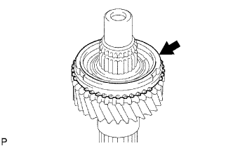
Using SST and a press, install a new output shaft center bearing to the output shaft.
- SST
- 09316-60011 ( 09316-00031 )
Note
Install so that the snap ring groove of the bearing will face to the rear side.
-
-
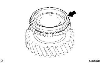
INSTALL 5TH GEAR
-
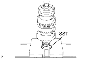
Using SST and a press, install the 5th gear to the output shaft.
- SST
- 09316-60011 ( 09316-00031 )
Note
-
Check that the 5th gear and the spline of the output shaft match before installing.
-
Put the convex part of the gear to the front side.
-
-
INSPECT 1ST GEAR THRUST CLEARANCE
-
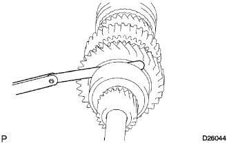
Using a feeler gauge, check the thrust clearance of the 1st gear.
Standard clearance 0.20 to 0.45 mm (0.0079 to 0.0177 in.)
-
-
INSPECT 2ND GEAR THRUST CLEARANCE
-
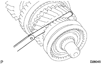
Using a feeler gauge, check the thrust clearance of the 2nd gear.
Standard clearance 0.10 to 0.25 mm (0.0039 to 0.0098 in.)
-
-
INSPECT 3RD GEAR THRUST CLEARANCE
-
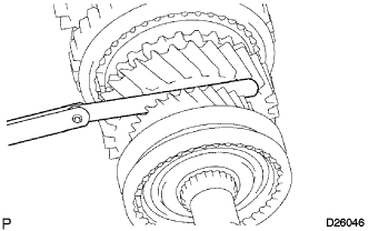
Using a feeler gauge, check the thrust clearance of the 3rd gear.
Standard clearance 0.10 to 0.25 mm (0.0039 to 0.0098 in.)
-
-
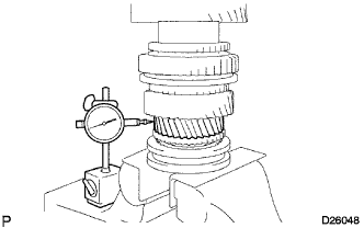
INSPECT 1ST GEAR RADIAL CLEARANCE
-
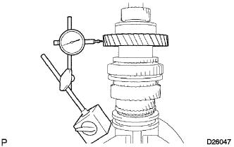
Using a dial indicator, check the radial clearance of the 1st gear.
Standard clearance 0.020 to 0.073 mm (0.0008 to 0.0029 in.) If the clearance is out of the specification, replace the 1st gear needle roller bearing with a new one.
-
-
INSPECT 2ND GEAR RADIAL CLEARANCE
-
Using a dial indicator, check the radial clearance of the 2nd gear.
Standard clearance 0.015 to 0.068mm (0.0006 to 0.0027 in.) If the clearance is out of the specification, replace the 2nd gear needle roller bearing with a new one.
-
-
INSPECT 3RD GEAR RADIAL CLEARANCE
-
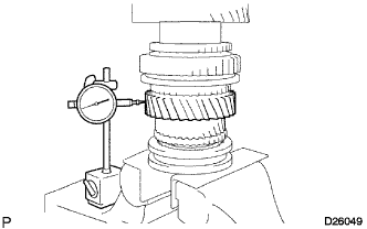
Using a dial indicator, check the radial clearance of the 3rd gear.
Standard clearance 0.015 to 0.068 mm (0.0006 to 0.0027 in.) If the clearance is out of the specification, replace the 3rd gear needle roller bearing with a new one.
-