GENERATOR REASSEMBLY

-
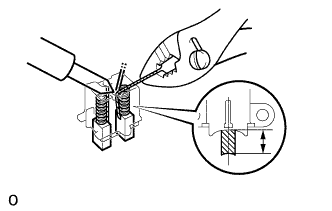
INSTALL BRUSH
-
Run the wire to a new brush through the spring and the hole in the holder, and insert the spring and brush into the holder.
-
Solder the brush wire to the holder at the specified exposed length.
Exposed length 9.5 - 11.5 mm (0.374 - 0.453 in.) -
Check that the brush moves smoothly.
-
Cut off the excess wire.
-
Apply insulation paint to the soldered area.
-
-
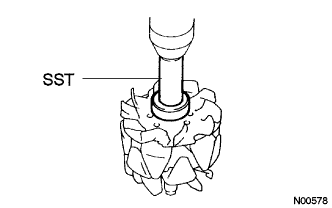
INSTALL ROTOR BEARING (Front)
-
Using SST and a press, press in a new bearing.
- SST
- 09950-60010 ( 09951-00280 )
- 09950-70010 ( 09951-07100 )
-
Install the bearing retainer with the 4 bolts.
- Torque:
- 2.6 N*m { 7 kgf*cm, 23 ft.*lbf }
-
-
INSTALL ROTOR BEARING (Rear)
-
Install the bearing cover (inside).
-
Using SST and a press, press in a new bearing.
- SST
- 09820-00030
-
Using SST, push in the bearing cover (outside).
- SST
- 09285-76010
-
-
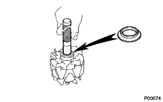
INSTALL GENERATOR ROTOR ASSEMBLY
-
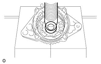
INSTALL RECTIFIER END FRAME
-
Place the generator washer on the rotor.
-
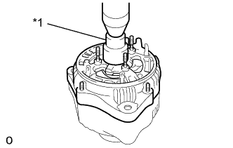
Text in Illustration *1 29 mm socket wrench Using a 29 mm socket wrench and press, slowly press in the rectifier end frame.
-
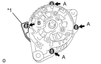
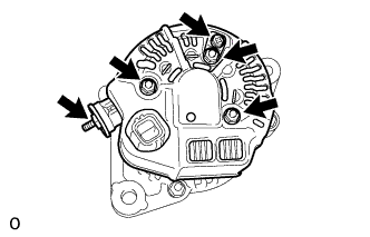
Text in Illustration *1 Cord Clip Install the cord clip and 4 nuts.
- Torque:
- 4.5 N*m { 46 kgf*cm, 40 in.*lbf, for nut A }
- 5.4 N*m { 55 kgf*cm, 48 in.*lbf, for nut B }
-
-
INSTALL GENERATOR HOLDER W/RECTIFIER
-
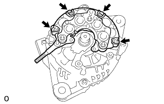
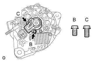
Install the rectifier holder with the 4 screws.
- Torque:
- 1.96 N*m { 20 kgf*cm, 17 in.*lbf }
-
-
INSTALL GENERATOR REGULATOR ASSEMBLY
-
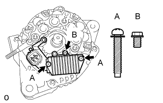
Install the regulator and 3 screws.
- Torque:
- 1.96 N*m { 20 kgf*cm, 17 in.*lbf }
-
-
INSTALL GENERATOR BRUSH HOLDER ASSEMBLY
-
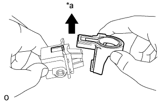
Install the brush holder cover.
Text in Illustration *a Upward Note
Be careful brush holder direction.
-
Install the brush holder and 2 screws.
- Torque:
- 1.96 N*m { 20 kgf*cm, 17 in.*lbf }
Note
Be careful of the holder installation direction.
-
-
INSTALL REAR END COVER
-
Install the end cover and plate terminal with the bolt and 3 nuts.
- Torque:
- 4.4 N*m { 45 kgf*cm, 39 in.*lbf, for nut }
- 3.9 N*m { 40 kgf*cm, 34 in.*lbf, for bolt }
-
Install the terminal insulator with the nut.
- Torque:
- 4.1 N*m { 42 kgf*cm, 36 in.*lbf }
-
-
INSTALL GENERATOR W/CLUTCH PULLEY
-
Install the pulley by hand.
-
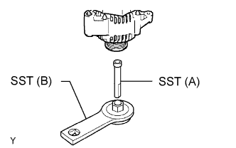
Install SST to the pulley and vise as shown in the illustration.
- SST
- 09820-63021 ( 09821-63011, 09821-63020 )
-
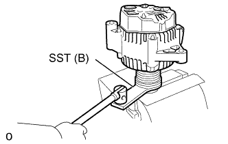
Turn SST (B) counterclockwise, tighten the pulley.
- SST
- 09820-63021 ( 09821-63011, 09821-63020 )
- Torque:
- 110.5 N*m { 1125 kgf*cm, 81 ft.*lbf }
-
-
INSPECT ROTOR BEARING
-
Check that rotor rotates smoothly.
-