GENERATOR INSPECTION

-
INSPECT GENERATOR W/CLUTCH PULLEY
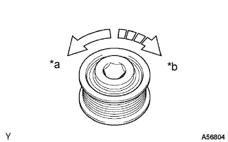
Text in Illustration *a Free *b Lock
-
When rotating the pulley, check that it turns clockwise and it does not turn counterclockwise.
-
-
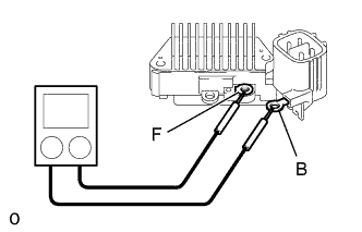
INSPECT GENERATOR REGULATOR ASSEMBLY
-
Using an ohmmeter, check the continuity between terminals F and B.
Standard When the positive and negative poles between terminals F and B are exchanged, there is continuity in one way but no continuity in another way. If the continuity is not as specified, replace the regulator.
-
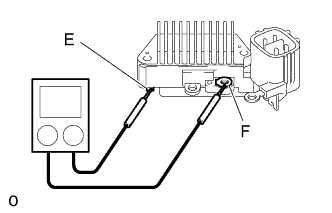
Using an ohmmeter, check the continuity between terminals F and E.
Standard When the positive and negative poles between terminals F and E are exchanged, there is continuity in one way but no continuity in another way. If the continuity is not as specified, replace the regulator.
-
-
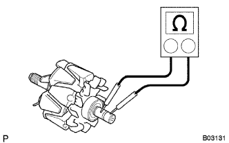
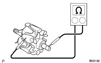
INSPECT GENERATOR ROTOR ASSEMBLY
-
Check the rotor for open circuit.
-
Using an ohmmeter, check that there is continuity between the slip rings.
Standard resistance 2.1 - 2.5 at 20°C (68°F) If there is no continuity, replace the rotor.
-
-
Check the rotor for ground.
-
Using an ohmmeter, check that there is no continuity between the slip ring and rotor.
If there is continuity, replace the rotor.
-
-
Check that the slip rings are not rough or scored.
If rough or scored, replace the rotor.
-
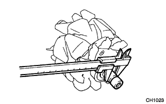
Using vernier calipers, measure the slip ring diameter.
Standard diameter 14.2 - 14.4 mm (0.559 - 0.567 in.) Minimum diameter 12.8 mm (0.504 in.) If the diameter is less than the minimum, replace the rotor.
-
-
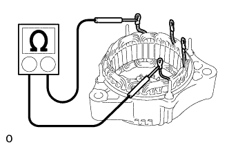
INSPECT RECTIFIER END FRAME
-
Check the stator for open circuit.
-
Using an ohmmeter, check that there is continuity between the coil leads.
If there is no continuity, replace the end frame.
-
-
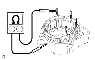
Check the stator for ground.
-
Using an ohmmeter, check that there is no continuity between the coil lead and drive end frame.
If there is continuity, replace the end frame.
-
-
-
INSPECT GENERATOR BRUSH HOLDER ASSEMBLY
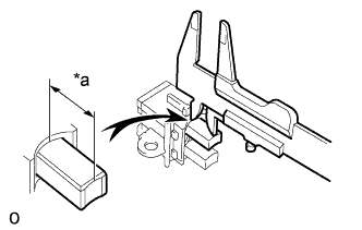
Text in Illustration *a Length
-
Using vernier calipers, measure the exposed brush length.
Standard exposed length 9.5 - 11.5 mm (0.374 - 0.453 in.) Minimum exposed length 1.5 mm (0.059 in.)
-
-
INSPECT GENERATOR HOLDER W/RECTIFIER
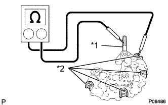
Text in Illustration *1 Positive Terminal *2 Rectifier Terminal
-
Check the positive (+) rectifier.
-
Using an ohmmeter, connect one tester probe to the positive (+) terminal and the other to each rectifier terminal.
-
Reverse the polarity of the tester probes and repeat step (1).
-
Check that one shows continuity and the other shows no continuity.
If the continuity is not as specified, replace the rectifier holder.
-
-
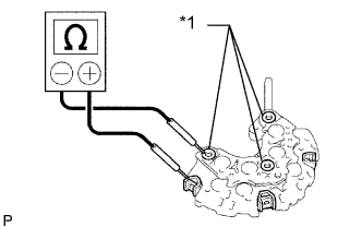
Text in Illustration *1 Negative Terminal Check the negative (-) rectifier.
-
Using an ohmmeter, connect one tester probe to each negative (-) terminal and the other to each rectifier terminal.
-
Reverse the polarity of the tester probes and repeat step (1).
-
Check that one shows continuity and the other shows no continuity.
If the continuity is not as specified, replace the rectifier holder.
-
-
-
INSPECT ROTOR BEARING
-
Check the bearing is not rough or worn.
If necessary, replace the bearing.
-