GENERATOR (w/ DPF) INSTALLATION
-
INSTALL GENERATOR ASSEMBLY (for LHD)
-
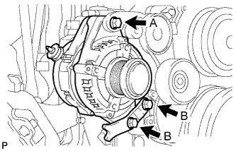
Temporarily install the generator assembly and generator bracket with the 3 bolts.
-
Tighten the 3 bolts to the specified torque.
- Torque:
- 62 N*m { 632 kgf*cm, 46 ft.*lbf, for bolt A }
- 36 N*m { 367 kgf*cm, 27 ft.*lbf, for bolt B }
-
Install the wire harness with the nut to terminal B.
- Torque:
- 9.8 N*m { 100 kgf*cm, 87 in.*lbf }
-
Install the terminal cap.
-
Connect the generator connector.
-
Apply a small amount of engine oil to a new O-ring and install it to the engine oil level dipstick guide.
-
Install the engine oil level dipstick guide with the bolt.
- Torque:
- 8.0 N*m { 82 kgf*cm, 71 in.*lbf }
-
Install the engine oil level dipstick sub-assembly.
-
Install the engine wire harness with the 2 bolts and connect the 2 connectors.
- Torque:
- 8.0 N*m { 82 kgf*cm, 71 in.*lbf }
-
-
INSTALL GENERATOR ASSEMBLY (for RHD)
-
Temporarily install the generator assembly and generator bracket with the 3 bolts.
-
Tighten the 3 bolts to the specified torque.
- Torque:
- 62 N*m { 632 kgf*cm, 46 ft.*lbf, for bolt A }
- 36 N*m { 367 kgf*cm, 27 ft.*lbf, for bolt B }
-
Install the wire harness with the nut to terminal B.
- Torque:
- 9.8 N*m { 100 kgf*cm, 87 in.*lbf }
-
Install the terminal cap.
-
Connect the generator connector.
-
Apply a small amount of engine oil to a new O-ring and install it to the engine oil level dipstick guide.
-
Install the engine wire harness with the 2 bolts and connect the connector.
- Torque:
- 8.0 N*m { 82 kgf*cm, 71 in.*lbf }
-
-
INSTALL FAN AND GENERATOR V BELT
-
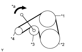
Use the pulley set bolt of the tensioner to rotate the tensioner pulley clockwise, and then install the V belt.
Text in Illustration *1 Fan Pulley *2 Crankshaft *3 Tensioner *4 Generator *a Turn Note
Make sure that the V belt is set properly at each pulley.
-
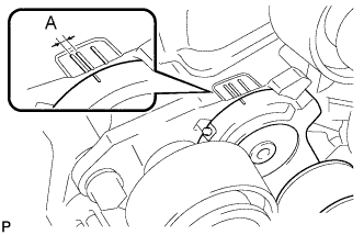
Make sure that the indicator mark of the tensioner is within range A, as shown in the illustration.
-
-
INSTALL NO. 1 AIR HOSE
-
Connect the No. 1 air hose and tighten the hose clamp.
-
-
INSTALL ENGINE SIDE COVER SUB-ASSEMBLY RH (for Double Cab)
-
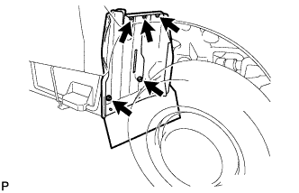
for Double Cab:
Install the engine side cover RH with the 4 bolts.
- Torque:
- 12 N*m { 122 kgf*cm, 9 ft.*lbf }
-
for Single Cab:
Install the engine side cover RH with the 3 bolts.
- Torque:
- 12 N*m { 122 kgf*cm, 9 ft.*lbf }
-
-
INSTALL FENDER SIDE APRON SUB-ASSEMBLY RH (for Double Cab)
-
Install the fender side apron sub-assembly RH with the 5 bolts.
- Torque:
- 5.0 N*m { 51 kgf*cm, 44 in.*lbf }
-
-
CONNECT CABLE TO NEGATIVE BATTERY TERMINAL
- Torque:
- 6.4 N*m { 65 kgf*cm, 56 in.*lbf }