STARTER (for 2.2 kW Type) REASSEMBLY

-
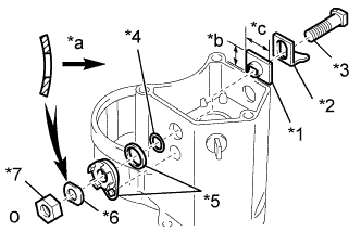
INSTALL STARTER TERMINAL KIT
-
Temporarily install new terminal 30 kit parts.
Text in Illustration *1 Terminal insulator (inside) *2 Contact plate *3 Terminal bolt *4 O-ring *5 Packing and terminal insulator (outside) *6 Wave washer *7 Terminal nut *a Inside *b Short *c Long Tech Tips
-
Install the packing to the terminal insulator, and install them.
-
Match the protrusion of the insulator with the indentation of the housing.
-
-
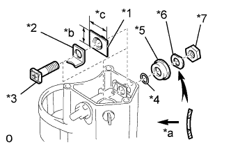
Text in Illustration *1 Terminal insulator (inside) *2 Contact plate *3 Terminal bolt *4 O-ring *5 Terminal insulator (outside) *6 Wave washer *7 Terminal nut *a Inside *b Short *c Long Temporarily install these new terminal C kit parts.
-
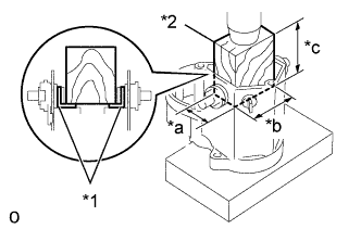
Text in Illustration *1 Contact Plate *2 Wooden Block *a 20 mm *b 37 mm *c 40 mm Tighten terminal nuts.
-
Put a wooden block on the contact plate and press it down with a hand press.
Dimensions of wooden block 20 x 37 x 40 mm (0.79 x 1.46 x 1.57 in.) Press force 981 N (100 kgf, 221 lbf) Note
-
Check the diameter of the hand press ram. Then calculate the gauge pressure of the press when 981 N (100 kgf, 221 lbf) of force is applied.

-
If the contact plate is not pressed down with the specified pressure, the contact plate may tilt due to coil deformation or the tightening of the nut.
-
-
-
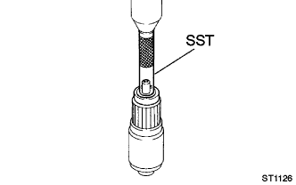
Using SST, tighten the nuts.
- Torque:
- 17 N*m { 173 kgf*cm, 13 ft.*lbf }
Note
If the nut is over tightened, it may cause cracks on the inside of the insulator.
-
Clean the contact surfaces of the remaining contact plate and plunger with a dry shop rag.
-
Reinstall the plunger, a new gasket, the end cover and lead clamp with the 3 bolts.
- Torque:
- 3.6 N*m { 37 kgf*cm, 32 in.*lbf }
-
-
INSTALL STARTER BEARING (Front)
-
Using SST and a press, press in a new bearing.
- SST
- 09201-41020
-
-
INSTALL STARTER BEARING (Rear)
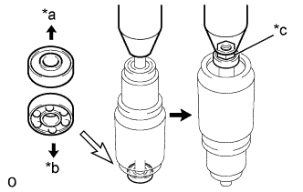
Text in Illustration *a Upward *b Downward *c 10 mm nut
-
Using a 10 mm (for thread diameter) nut and press, install a new bearing.
Note
Be careful of the bearing direction.
-
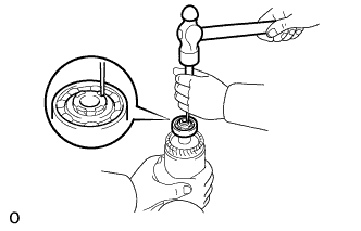
Using a punch, stake the armature shaft.
-
-
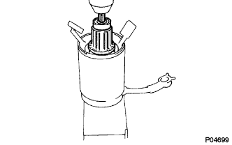
INSTALL STARTER ARMATURE ASSEMBLY
-
Using a press, install the armature assembly.
-
-
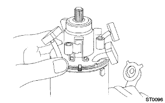
INSTALL STARTER BRUSH HOLDER ASSEMBLY
-
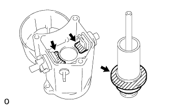
Align the claw of the brush holder with the claw groove of the starter yoke assembly.
-
Place the brush holder on the starter yoke assembly.
-
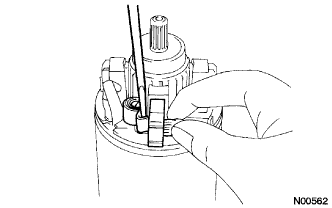
Using a screwdriver, hold the brush spring back.
-
Connect the brush into the brush holder.
-
Connect the 4 brushes.
Note
Check that the positive (+) lead wires are not grounded.
-
Install a new O-ring to the groove of the starter yoke.
-
-
INSTALL MAGNET STARTER SWITCH ASSEMBLY
-
Apply grease to the steel ball, return spring, clutch rollers and starter idler pinions.
-
Install the steel ball.
-
Insert the return spring into the magnet starter switch hole.
-
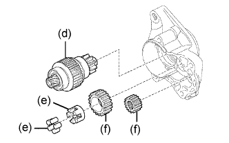
Install the starter clutch sub-assembly.
-
Install the 5 clutch rollers and retainer.
-
Install the 2 starter idler pinions.
-
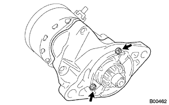
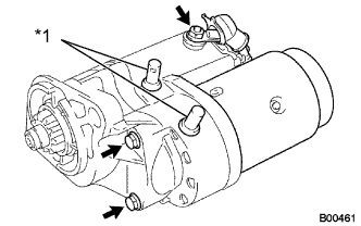
Install the starter housing to the magnet switch assembly with the 2 screws.
- Torque:
- 9.3 N*m { 95 kgf*cm, 82 in.*lbf }
-
-
INSTALL STARTER YOKE ASSEMBLY
Text in Illustration *a Align
-
Install a new O-ring to the groove of the starter yoke assembly.
-
Align the claws of the brush holder with the grooves of the magnet starter switch.
-
Install the starter yoke assembly with the armature assembly.
-
Align the punch mark of the starter yoke with the line of the magnet starter switch.
-
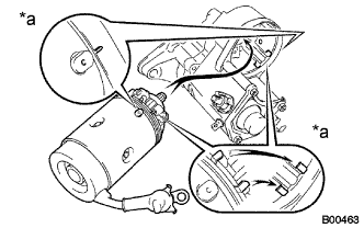
Text in Illustration *1 New Dust Protector Install the 2 new O-rings and 2 long bolts.
- Torque:
- 12.7 N*m { 130 kgf*cm, 9 ft.*lbf }
-
Connect the terminal C wire with the nut.
- Torque:
- 5.9 N*m { kgf*cm, in.*lbf }
-
Install 2 new dust protectors.
-
Install the terminal 50 wire with the screw.
- Torque:
- 3.6 N*m { 37 kgf*cm, 32 in.*lbf }
-