PRE-HEATING SYSTEM Pre-heating Control Circuit
DESCRIPTION
The glow plug is mounted inside the engine combustion chamber. To ensure efficient engine starting with a cold engine, the preheating timer turns on the glow relay and permits the current to flow through the glow plug based on the preheating timer calculated time. The glow plug is then heated, enabling fuel combustion with a cold engine.
WIRING DIAGRAM
Refer to System Diagram Click here.
INSPECTION PROCEDURE
Note
Inspect the fuses of circuits related to this system before performing the following inspection procedure.
PROCEDURE
-
CHECK GLOW RELAY (VOLTAGE)
-
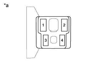
Text in Illustration *a Front view of wire harness connector
(to Glow Relay)
Remove the glow relay.
-
Measure the voltage according to the value(s) in the table below.
Standard Voltage Tester Connection Condition Specified Condition 1 - Body ground Always 11 to 14 V -
Reinstall the glow relay.
NG 
REPAIR OR REPLACE HARNESS OR CONNECTOR (GLOW RELAY - BATTERY)
OK 
-
-
CHECK GLOW RELAY (VOLTAGE)
-
Text in Illustration *a Front view of wire harness connector
(to Glow Relay)
Remove the glow relay.
-
Turn the ignition switch to ON.
-
Measure the voltage according to the value(s) in the table below.
Standard Voltage Tester Connection Switch Condition Specified Condition 3 - Body ground Ignition switch ON 11 to 14 V Tech Tips
Power voltage (12 V) is applied for approximately 18 seconds after turning the ignition switch on.
-
Reinstall the glow relay.
NG 
CHECK PREHEATING TIMER Click here
OK
-
-
CHECK GLOW RELAY (VOLTAGE)
-
Text in Illustration *a Front view of wire harness connector
(to Glow Relay)
Remove the glow relay.
-
Measure the voltage according to the value(s) in the table below.
Standard Voltage Tester Connection Condition Specified Condition 3 - Body ground Engine cranking 11 to 14 V -
Reinstall the glow relay.
NG
CHECK HARNESS AND CONNECTOR (IGNITION SWITCH ASSEMBLY - GLOW RELAY) Click here
OK
-
-
INSPECT GLOW RELAY
-
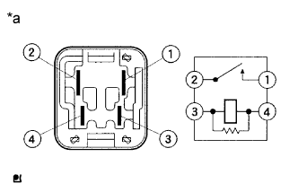
Text in Illustration *a Component without harness connected
(Glow Relay)
Remove the glow relay.
-
Measure the resistance according to the value(s) in the table below.
Standard Resistance Tester Connection Condition Specified Condition 1 - 2 Always 10 kΩ or higher 3 - 4 Always Below 1 Ω -
Reinstall the glow relay.
NG
REPLACE GLOW RELAY
OK
-
-
CHECK HARNESS AND CONNECTOR (GLOW RELAY - BODY GROUND)
-
Text in Illustration *a Front view of wire harness connector
(to Glow Relay)
Remove the glow relay.
-
Measure the resistance according to the value(s) in the table below.
Standard Resistance Tester Connection Condition Specified Condition 4 - Body ground Always Below 1 Ω -
Reinstall the glow relay.
NG
REPAIR OR REPLACE HARNESS OR CONNECTOR (GLOW RELAY - BODY GROUND)
OK
-
-
CHECK HARNESS AND CONNECTOR (GLOW RELAY - GLOW PLUG ASSEMBLY)
-
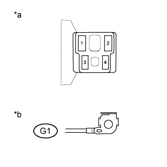
Text in Illustration *a Front view of wire harness connector
(to Glow Relay)
*b Front view of wire harness connector
(to Glow Plug)
Remove the glow relay.
-
Disconnect the G1 glow plug assembly connector.
-
Measure the resistance according to the value(s) in the table below.
Standard Resistance (Check for Open) Tester Connection Condition Specified Condition 2 - G1-1 Always Below 1 Ω Standard Resistance (Check for Short) Tester Connection Condition Specified Condition 2 or G1-1 - Body ground Always 10 kΩ or higher -
Reconnect the G1 glow plug assembly connector.
-
Reinstall the glow relay.
NG
REPAIR OR REPLACE HARNESS OR CONNECTOR (GLOW RELAY - GLOW PLUG ASSEMBLY)
OK
-
-
INSPECT GLOW PLUG ASSEMBLY (RESISTANCE)
-
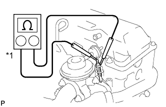
Text in Illustration *1 Ohmmeter Remove the glow plug assembly connector.
-
Measure the resistance according to the value(s) in the table below.
Standard Resistance Tester Connection Condition Specified Condition Glow plug terminal - Body ground 20°C (68°F) 0.72 Ω Tech Tips
If any of the glow plugs has an open circuit, the engine power is insufficient only when the engine is cold.
Note
-
Exercise extreme care not to damage the glow plug pipes. Damaging them could cause an open circuit, or shorten the life of the glow plugs.
-
Keep the glow plugs free of oil and fuel while cleaning.
-
Wipe any oil off of the terminal and Bakelite washer with a clean, dry cloth during inspection.
-
Do not apply more than 11 V to the glow plugs as doing so may cause an open circuit.
-
-
Reinstall the glow plug assembly connector.
NG
REPLACE GLOW PLUG ASSEMBLY
OK
-
-
CHECK GLOW PLUG ASSEMBLY (INSTALLATION)
-
Check the glow plug assembly installation.
OK Glow plug assemblies are installed securely. - Torque:
- 13 N*m { 130 kgf*cm, 9 ft.*lbf }
NG
SECURELY REINSTALL GLOW PLUG ASSEMBLY
OK 
SYSTEM IS OK
-
-
CHECK PREHEATING TIMER
-
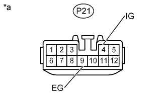
Text in Illustration *a Front view of wire harness connector
(to Preheating Timer)
Disconnect the P21 preheating timer connector.
-
Turn the ignition switch to ON.
-
Measure the voltage according to the value(s) in the table below.
Standard Voltage Tester Connection Switch Condition Specified Condition P21-4 (IG) - P21-9 (EG) Ignition switch ON 11 to 14 V -
Reconnect the P21 preheating timer connector.
NG
CHECK HARNESS AND CONNECTOR (PREHEATING TIMER - IGNITION SWITCH ASSEMBLY) Click here
OK
-
-
CHECK HARNESS AND CONNECTOR (PREHEATING TIMER - GLOW RELAY)
-
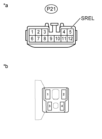
Text in Illustration *a Front view of wire harness connector
(to Preheating Timer)
*b Front view of wire harness connector
(to Glow Relay)
Disconnect the P21 preheating timer connector.
-
Remove the glow relay.
-
Measure the resistance according to the value(s) in the table below.
Standard Resistance (Check for Open) Tester Connection Condition Specified Condition P21-5 (SREL) - 3 Always Below 1 Ω Standard Resistance (Check for Short) Tester Connection Condition Specified Condition P21-5 (SREL) or 3 - Body ground Always 10 kΩ or higher -
Reconnect the P21 preheating timer connector.
-
Reinstall the glow relay.
NG
REPAIR OR REPLACE HARNESS OR CONNECTOR (PREHEATING TIMER - GLOW RELAY)
OK
REPLACE PREHEATING TIMER
-
-
CHECK HARNESS AND CONNECTOR (IGNITION SWITCH ASSEMBLY - GLOW RELAY)
-
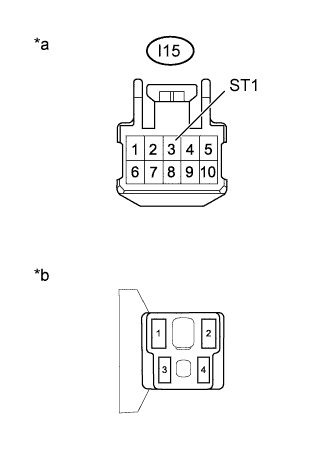
Text in Illustration *a Front view of wire harness connector
(to Ignition Switch Assembly)
*b Front view of wire harness connector
(to Glow Relay)
Disconnect the I15 ignition switch assembly connector.
-
Remove the glow relay.
-
Measure the resistance according to the value(s) in the table below.
Standard Resistance (Check for Open) Tester Connection Condition Specified Condition I15-3 (ST1) - 3 Always Below 1 Ω Standard Resistance (Check for Short) Tester Connection Condition Specified Condition I15-3 (ST1) or 3 - Body ground Always 10 kΩ or higher -
Reconnect the I15 ignition switch assembly connector.
-
Reinstall the glow relay.
NG
REPAIR OR REPLACE HARNESS OR CONNECTOR (IGNITION SWITCH ASSEMBLY - GLOW RELAY)
OK
-
-
INSPECT IGNITION SWITCH ASSEMBLY
-
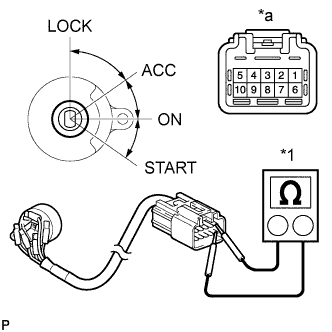
Text in Illustration *1 Ohmmeter *a Component without harness connected
(Ignition Switch Assembly)
Measure the resistance according to the value(s) in the table below.
Standard resistance Tester Connection Condition Specified Condition Between all terminals LOCK 10 kΩ or higher 4 (ACC) - 9 (AM1) ACC Below 1 Ω 4 (ACC) - 9 (AM1) - 10 (IG1)
5 (AM2) - 8 (IG2)
ON Below 1 Ω 3 (ST1) - 9 (AM1) - 10 (IG1)
5 (AM2) - 8 (IG2)
START Below 1 Ω
NG
REPLACE IGNITION SWITCH ASSEMBLY
OK
REPAIR OR REPLACE HARNESS OR CONNECTOR (IGNITION SWITCH ASSEMBLY - BATTERY)
-
-
CHECK HARNESS AND CONNECTOR (PREHEATING TIMER - IGNITION SWITCH ASSEMBLY)
-
Disconnect the P21 preheating timer connector.
-
Disconnect the I15 ignition switch assembly connector.
-
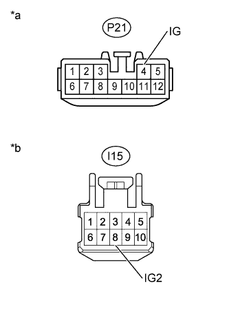
Text in Illustration *a Front view of wire harness connector
(to Preheating Timer)
*b Front view of wire harness connector
(to Ignition Switch Assembly)
Measure the resistance according to the value(s) in the table below.
Standard Resistance (Check for Open) Tester Connection Condition Specified Condition P21-4 (IG) - I15-8 (IG2) Always Below 1 Ω Standard Resistance (Check for Short) Tester Connection Condition Specified Condition P21-4 (IG) or I15-8 (IG2) - Body ground Always 10 kΩ or higher -
Reconnect the I15 ignition switch assembly connector.
-
Reconnect the P21 preheating timer connector.
NG
REPAIR OR REPLACE HARNESS OR CONNECTOR (PREHEATING TIMER - IGNITION SWITCH ASSEMBLY)
OK
-
-
INSPECT IGNITION SWITCH ASSEMBLY
-
Text in Illustration *1 Ohmmeter *a Component without harness connected
(Ignition Switch Assembly)
Measure the resistance according to the value(s) in the table below.
Standard resistance Tester Connection Condition Specified Condition Between all terminals LOCK 10 kΩ or higher 4 (ACC) - 9 (AM1) ACC Below 1 Ω 4 (ACC) - 9 (AM1) - 10 (IG1)
5 (AM2) - 8 (IG2)
ON Below 1 Ω 3 (ST1) - 9 (AM1) - 10 (IG1)
5 (AM2) - 8 (IG2)
START Below 1 Ω
NG
REPLACE IGNITION SWITCH ASSEMBLY
OK
REPAIR OR REPLACE HARNESS OR CONNECTOR (IGNITION SWITCH ASSEMBLY - BATTERY)
-