GENERATOR REASSEMBLY

-
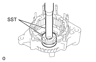
INSTALL ROTOR BEARING (Front)
-
Using SST and a press, press in a new bearing.
- SST
- 09950-60010 ( 09951-00400 )
-
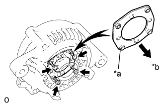
Text in Illustration *a Protrusion *b Front Place the bearing retainer on the drive end frame with the protrusions facing forward.
-
Install the bearing retainer with the 4 screws.
- Torque:
- 2.6 N*m { 26.5 kgf*cm, 23 in.*lbf }
-
Install the oil seal (See step 19).
- SST
- 09950-60010 ( 09951-00400 )
- 09950-70010 ( 09951-07100 )
-
-
INSTALL ROTOR BEARING (Rear)
-
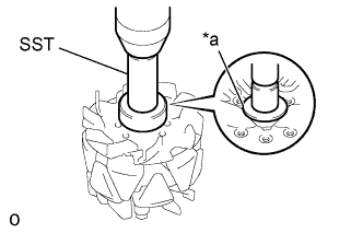
Place the bearing cover (inside) on the rotor.
Text in Illustration *a Bearing Cover (Inside) -
Using SST and a press, press in a new bearing.
- SST
- 09820-00030
-
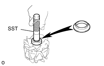
Using SST, push in the bearing cover (outside).
- SST
- 09285-76010
-
-
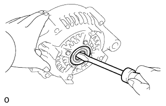
REMOVE OIL SEAL
-
Using a screwdriver, pry out the oil seal.
-
-
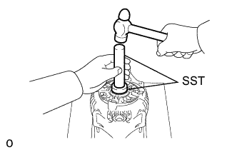
INSTALL OIL SEAL
-
Using SST and hammer, tap in the oil seal.
- SST
- 09950-60010 ( 09951-00340 )
- 09950-70010 ( 09951-07100 )
-
-
INSTALL GENERATOR ROTOR ASSEMBLY
-
Using a press, press in the rotor.
-
-
INSTALL RECTIFIER END FRAME
-
Place the alternator washer to the rotor.
-
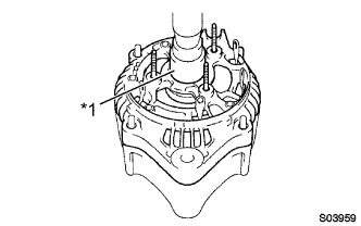
Text in Illustration *1 Socket Wrench (27 mm) Using a 27 mm socket wrench and press, slowly press in the rectifier end frame.
-
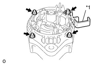
Text in Illustration *1 Cold Clamp Install the cord clamp and 4 nuts.
- Torque:
- 4.5 N*m { 46 kgf*cm, 40 in.*lbf }
-
-
INSTALL GENERATOR HOLDER W/RECTIFIER
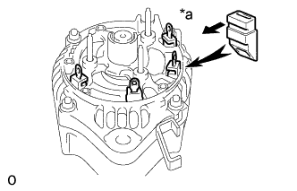
Text in Illustration *a Inside
-
Install the 4 rubber insulators on the lead wires.
Note
Be careful of the rubber insulators installation direction.
-
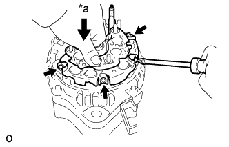
Text in Illustration *a Push Install the rectifier holder while pushing it with the 4 screws.
- Torque:
- 2.9 N*m { 30 kgf*cm, 26 in.*lbf }
-
-
INSTALL GENERATOR REGULATOR ASSEMBLY
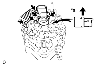
Text in Illustration *a Upward
-
Install the regulator assembly with the 3 screws.
-
-
INSTALL GENERATOR BRUSH HOLDER ASSEMBLY
-
Place the seal plate.
-
Install the brush holder assembly with the 2 screws.
-
Place the brush holder cover.
- Torque:
- 2.0 N*m { 20 kgf*cm, 18 in.*lbf }
-
-
INSTALL REAR END COVER
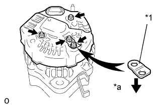
Text in Illustration *1 Plate Terminal *a Downward
-
Install the rear end cover and plate terminal with the bolt and 3 nuts.
- Torque:
- 4.4 N*m { 45 kgf*cm, 39 in.*lbf, for nut }
- 3.8 N*m { 39 kgf*cm, 34 in.*lbf, for bolt }
-
-
INSTALL VACUUM PUMP ASSEMBLY
-
Align the matchmarks and install the vacuum pump assembly with the 4 bolts.
- Torque:
- 7.8 N*m { 80 kgf*cm, 69 in.*lbf }
-
-
INSPECT ROTOR BEARING
-
Check that rotor rotates smoothly.
-