STARTER (for 2.2 kW Type) INSPECTION
-
INSPECT STARTER
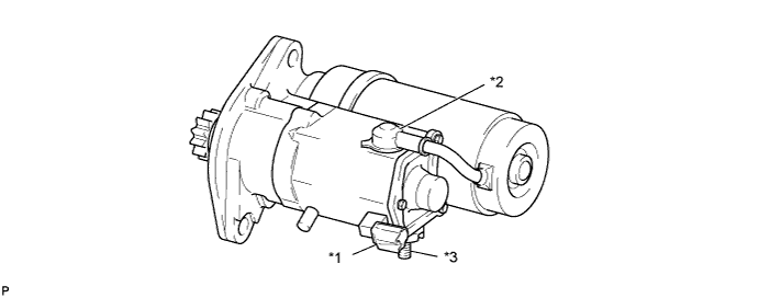
Text in Illustration *1 Terminal 50 *2 Terminal C *3 Terminal 30 - - CAUTION:
These tests must be performed within 3 to 5 seconds to prevent the coil from burning out.
-
Perform pull-in/holding test.
-
Remove the nut and disconnect the field coil lead wire from terminal C.
-
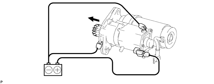
Connect the battery to the magnet switch as shown in the illustration. Then check that the clutch pinion gear moves outward.
-
Disconnect the negative (-) lead from terminal C. Check that the pinion gear remains out.
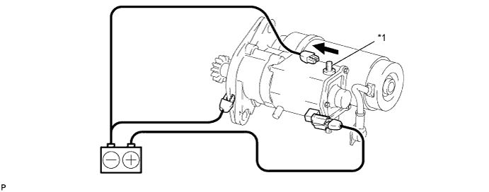
Text in Illustration *1 Terminal C - - -
Disconnect the negative (-) lead from the starter body. Check that the clutch pinion gear returns inward.
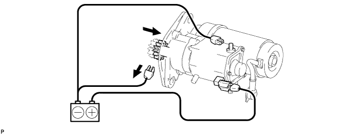
If the result is not as specified, replace the magnet starter switch assembly.
-
-
Perform operation test without load.
-
Install the field coil lead wire with the nut to the terminal C.
- Torque:
- 5.9 N*m { 60 kgf*cm, 52 in.*lbf }
-
Mount the starter in a vise.
-
Connect the battery and ammeter to the starter as shown in the illustration.
-
Check that the starter rotates smoothly and steadily while the pinion gear is out. Then measure the current.
Standard current 120 A or less at 11.5 V 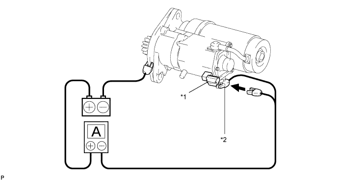
Text in Illustration *1 Terminal 50 *2 Terminal 30 If the result is not as specified, replace the starter.
-
-
-
INSPECT STARTER ARMATURE ASSEMBLY
-
Measure the resistance.
-
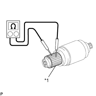
Text in Illustration *1 Commutator Measure the resistance between any 2 segments of the commutator.
Standard resistance Below 1 Ω If the result is not as specified, replace the starter armature assembly.
-
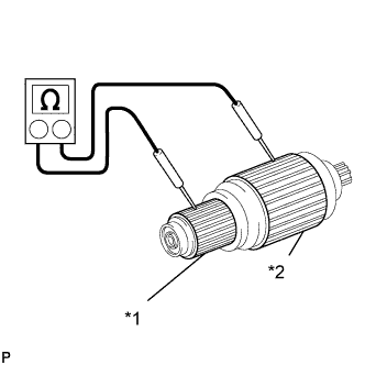
Text in Illustration *1 Commutator *2 Armature Coil Core Measure the resistance between each segment of the commutator and armature coil core.
Standard resistance 10 kΩ or higher If the result is not as specified, replace the starter armature assembly.
-
-
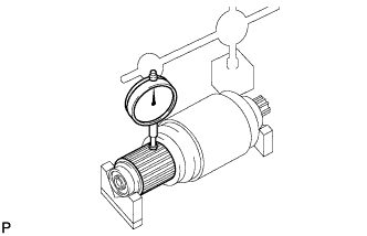
Inspect circle runout.
-
Place the armature on V-blocks.
-
Using a dial gauge, measure the circle runout.
Maximum circle runout 0.05 mm (0.0020 in.) If the circle runout is greater than the maximum, correct with sandpaper (#400) or replace the starter armature assembly.
-
-
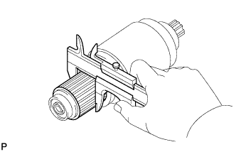
Using a vernier caliper, measure the commutator diameter.
Standard commutator diameter 35.0 mm (1.378 in.) Minimum commutator diameter 34.0 mm (1.339 in.) If the diameter is less than the minimum, replace the starter armature assembly.
-
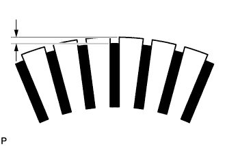
Measure the undercut depth of the commutator.
Standard undercut depth 0.7 mm (0.028 in.) Minimum undercut depth 0.2 mm (0.008 in.) If the undercut depth is less than the minimum, correct it with a hacksaw blade.
-
Inspect the bearings.
-
Check that the bearings rotate smoothly.
If the result is not as specified, replace the starter armature assembly.
-
-
-
INSPECT STARTER YOKE ASSEMBLY
-
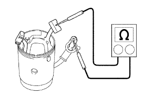
Inspect the field coil for an open circuit.
-
Measure the resistance between the lead wire and field coil brush lead.
Standard resistance Below 1 Ω If the result is not as specified, replace the starter yoke assembly.
-
-
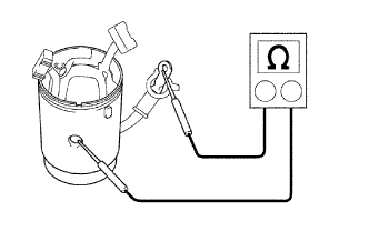
Inspect the ground.
-
Measure the resistance between the terminal C wire and starter yoke body.
-
Measure the resistance between the brushes and starter yoke body.
Standard resistance 10 kΩ or higher If the result is not as specified, replace the starter yoke assembly.
-
-
-
INSPECT BRUSH
-
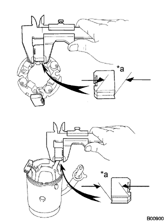
Text in Illustration *a Length Using a vernier caliper, measure the brush length.
Standard length 16.5 mm (0.650 in.) Minimum length 9.0 mm (0.354 in.) If the length is less than the minimum, replace the starter brush holder assembly and starter yoke assembly.
-
-
INSPECT STARTER BRUSH HOLDER ASSEMBLY
-
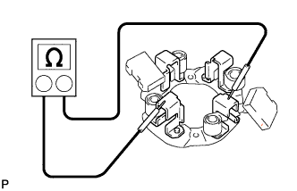
Inspect the brush insulation.
-
Using an ohmmeter, measure the resistance between the positive and negative brush holders.
Standard resistance 10 kΩ or higher If the result is not as specified, replace the starter brush holder assembly.
-
-
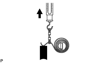
Take the pull scale reading the instant the brush spring separates from the brush.
Standard spring installed load 26.5 to 32.3 N (2.7 to 3.3 kgf, 5.9 to 7.3 lbf) Minimum spring installed load 17.6 N (1.8 kgf, 4.0 lbf) If the spring load is less than the minimum, replace the starter brush holder assembly.
-
-
INSPECT STARTER CLUTCH SUB-ASSEMBLY
-
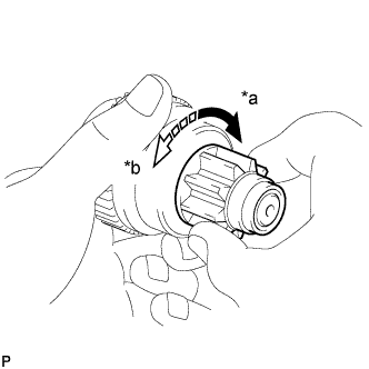
Text in Illustration *a Free *b Lock Rotate the pinion gear clockwise, and check that it turns freely. Try to rotate the pinion gear counterclockwise and check that it locks.
If necessary, replace the starter clutch sub-assembly.
-
-
INSPECT MAGNET STARTER SWITCH ASSEMBLY
-
Check if the pull-in coil has an open circuit.
-
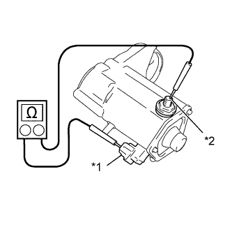
Text in Illustration *1 Terminal 50 *2 Terminal C Measure the resistance between terminals 50 and C.
Standard resistance Below 1 Ω If the result is not as specified, replace the magnet starter switch assembly.
-
-
Check if the hold-in coil has an open circuit.
-
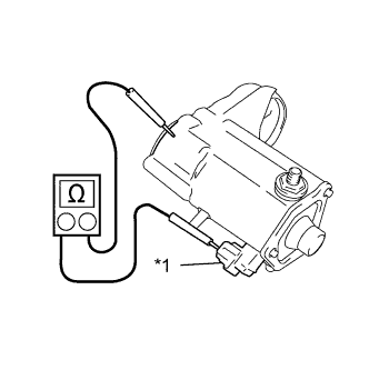
Text in Illustration *1 Terminal 50 Measure the resistance between terminal 50 and the switch body.
Standard resistance Below 2 Ω If the result is not as specified, replace the magnet starter switch assembly.
-
-