STARTER (for 2.0 kW Type) INSPECTION

-
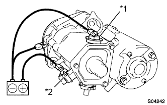
PERFORM PULL-IN/HOLDING TEST
-
Disconnect the lead wire from terminal C.
Text in Illustration *1 Terminal C *2 Terminal 50 -
Connect the battery to the magnetic switch as shown in the illustration.
-
Check that the pinion gear moves outside.
-
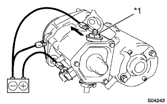
Text in Illustration *1 Terminal C Disconnect the negative lead from terminal C.
-
Check that the magnetic clutch keeps the pinion gear moving outside.
-
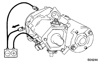
Disconnect the negative lead from the switch body.
-
Check that the pinion gear returns.
-
Reconnect the lead wire to the terminal C.
-
-
PERFORM OPERATION TEST WITHOUT LOAD
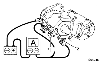
Text in Illustration *1 Terminal 50 *2 Terminal 30 Note
These tests must be performed within 5 seconds to prevent burning out the starter motor.
-
Connect the battery and ammeter to the starter as shown in the illustration.
-
Check that the pinion gear rotates smoothly.
-
Measure the current when the pinion gear rotates.
Standard current (at 11.5 V) 100 A or less If the current is not as specified, check the starter assembly.
-
-
INSPECT OPERATION
Note
These tests must be performed within 5 seconds to prevent burning out the starter motor.
-
Connect the battery and ammeter to the starter as shown in the illustration.
-
Check that the pinion gear rotates smoothly.
-
Measure the current when the pinion gear rotates.
Standard current (at 11.5 V) 100 A or less If the current is not as specified, check the starter assembly.
-
-
INSPECT STARTER ARMATURE ASSEMBLY
-
If the surface of the commutator is dirty or burned, polish the part with sandpaper (#400) or replace the armature.
-
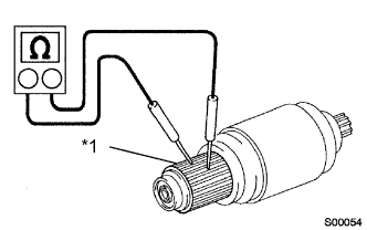
Check the commutator open circuit.
-
Using an ohmmeter, check that there is continuity between the segments of the commutator.
Text in Illustration *1 Commutator If there is no continuity between any segment, replace the armature.
-
-
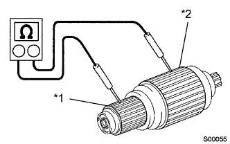
Text in Illustration *1 Commutator *2 Armature Core Check the commutator ground.
-
Using an ohmmeter, check that there is no continuity between the commutator and armature core.
If there is continuity, replace the armature.
-
-
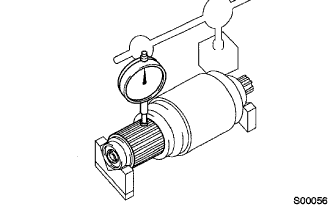
Check the commutator circle runout.
-
Place the armature on the V-blocks.
-
Using a dial gauge, measure the circle runout.
Maximum circle runout 0.05 mm (0.0020 in.) If the circle runout is greater than maximum, correct it with sandpaper (#400) or replace the armature.
-
-
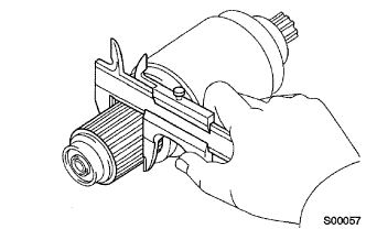
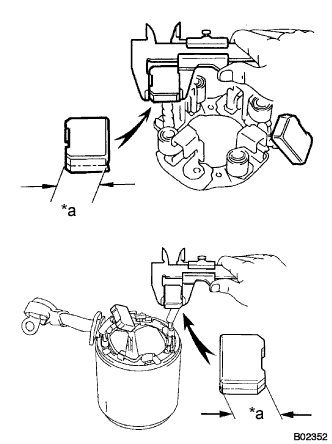
Using vernier calipers, measure the commutator diameter.
Diameter Standard 35.0 mm (1.378 in.) Minimum 34.0 mm (1.338 in.) -
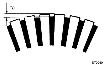
Text in Illustration *a Under Cut Depth Measure the undercut depth of commutator.
Depth Standard 0.7 mm (0.028 in.) Minimum 0.2 mm (0.008 in.) If the undercut depth is less than the minimum, correct it with a hacksaw blade.
-
-
INSPECT STARTER BEARING
-
Check that the bearings rotate smoothly.
If necessary, replace them.
-
-
INSPECT STARTER YOKE ASSEMBLY
-
Inspect for open circuit.
-
Check that there is continuity between the terminal C wire and brushes.
If there is no continuity, replace the starter yoke assembly.
-
-
Inspect for ground.
-
Check that there is no continuity between the brushes and starter yoke body.
-
Check that there is no continuity between the terminal C wire and starter yoke body.
If there is continuity, replace the starter yoke assembly.
-
-
Inspect the shunt coil for open circuit.
-
Measure the resistance between terminals.
Standard resistance 1.5 - 1.9 Ω at 20 °C(68 °F) If the resistance is not as specified, replace the starter yoke.
-
-
-
INSPECT BRUSH
-
Text in Illustration *a Length Using vernier calipers, measure the brush length.
Brush length Standard 15.0 mm (0.591 in.) Minimum 9.0 mm (0.354 in.) If the length is less than the minimum, replace the brush holder and starter yoke assembly.
-
-
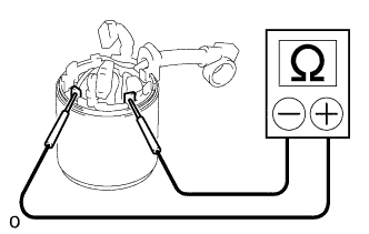
INSPECT STARTER BRUSH HOLDER ASSEMBLY

-
Using an ohmmeter, check that there is no continuity between the positive and negative brush holders.
Text in Illustration *1 Positive *2 Negative If there is continuity, replace the brush holder.
-
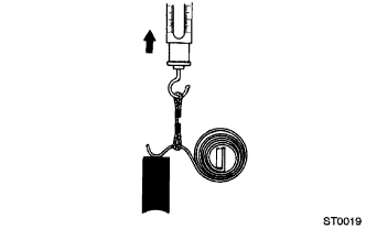
Using a pull scale, measure the brush spring load.
Brush length Standard 21.5 - 27.5 N (2.2 - 2.8 kgf, 4.9 - 6.2 lbf) Minimum 12.7 N (1.3 kgf, 2.7 lbf) If the spring load is less than the minimum, replace the brush springs.
-
-
INSPECT STARTER CLUTCH SUB-ASSEMBLY
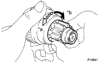
Text in Illustration *a Lock *b Free
-
Check that the starter clutch operates.
If the starter clutch is does not operate, replace it.
-
-
INSPECT MAGNET STARTER SWITCH ASSEMBLY
-
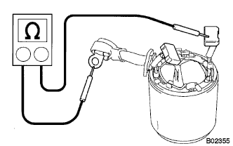
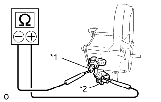
Check the pull-in coil continuity.
-
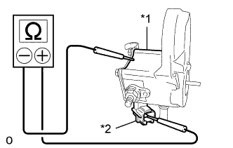
Using an ohmmeter, check that there is continuity between terminals 50 and C.
Text in Illustration *1 Terminal C *2 Terminal 50 If there is no continuity, replace the magnet starter switch assembly.
-
-
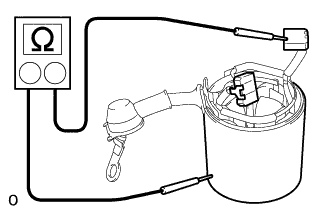
Text in Illustration *1 Switch Body *2 Terminal 50 Check the holding coil continuity.
-
Using an ohmmeter, check that there is continuity between terminals 50 and switch body.
If there is no continuity, replace the magnet starter switch assembly.
-
-
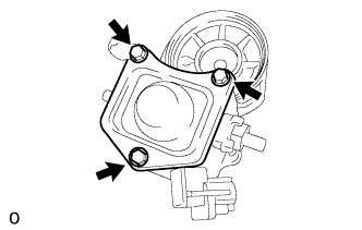
Inspect the contact plate.
-
Remove the 3 bolts, lead clamp, end cover, gasket and plunger.
-
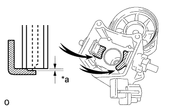
Text in Illustration *a Wear Using vernier calipers, measure the contact plate for depth of wear.
Maximum wear 0.9 mm (0.035 in.) If the depth of wear is greater than the maximum, replace the terminal kit parts. -
Install a new gasket, plunger, lead clamp and the end cover with the 3 bolts.
-
-