OIL PUMP INSTALLATION

-
INSTALL TIMING GEAR CASE ASSEMBLY (Oil Pump Assembly)
-
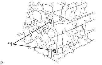
Text in Illustration *1 New O-ring Install the 2 new O-rings to the cylinder block groove of the timing gear case.
-
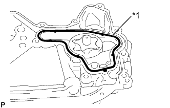
Text in Illustration *1 New Gasket Install a new gasket to the groove of the timing gear case.
-
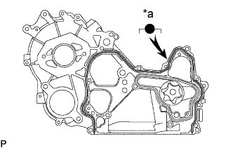
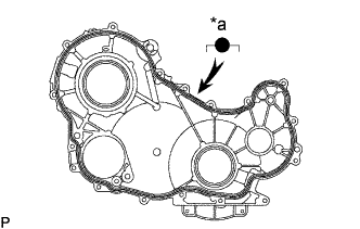
Text in Illustration *a Width: 3 - 5 mm Apply seal packing to the timing gear case as shown in the illustration.
Seal packing Toyota Genuine Seal Packing Black, Three Bond 1207B or equivalent
-
Install a nozzle that has been cut to a 3 - 5mm(0.16 - 0.20 in.) opening.
Tech Tips
Avoid applying an excessive amount to the surface.
-
Parts must be assembled within 5 minutes of application. Otherwise the material must be removed and reapplied.
-
Immediately remove nozzle from the tube and reinstall cap.
-
-
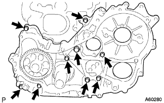
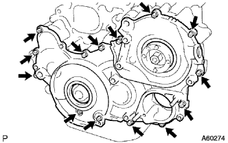
Install the timing gear case with the union bolt and 8 bolts.
- Torque:
- Union bolt
- 13 N*m { 130 kgf*cm, 9 ft.*lbf }
- Bolt
- 16 N*m { 160 kgf*cm, 12 ft.*lbf }
-
-
INSTALL OIL PAN SUB-ASSEMBLY
-
Remove any old packing (FIPG) material and be careful not to drop any oil on the contact surfaces of the oil pan and cylinder block.
-
Using a razor blade and gasket scraper, remove all the old packing (FIPG) material from the gasket surfaces and sealing groove.
-
Thoroughly clean all components to remove all the loose material.
-
Using a non-residue solvent, clean both sealing surfaces.
Note
Do not use a solvent which will affect the painted surfaces.
-
-
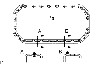
Text in Illustration *a Width: 3 - 5 mm Apply seal packing to the oil pan as shown in the illustration.
Seal packing Toyota Genuine Seal Packing Black, Three Bond 1207B or equivalent
-
Install a nozzle that has been cut to a 3 - 5mm(0.12 - 0.20 in.) opening.
-
Parts must be assembled within 5 minutes of application. Otherwise the material must be removed and reapplied.
-
Immediately remove nozzle from the tube and reinstall cap.
-
-
Install the oil pan with the 22 bolts and 2 nuts.
- Torque:
- 16 N*m { 165 kgf*cm, 12 ft.*lbf }
-
Remove the timing gear case plug.
-
Fill the engine oil into the oil pump.
-
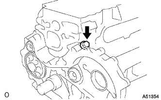
Remove the timing gear case plug.
-
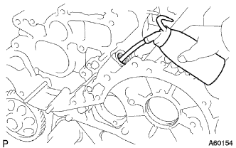
Pour in approx. 50 cc (3.15 cu in.) of engine oil into the oil pump.
-
-
Reinstall a new gasket and the screw plug.
- Torque:
- 41.5 N*m { 423 kgf*cm, 31 ft.*lbf }
-
-
INSTALL REAR END PLATE
-
INSTALL CYLINDER BROCK INSULATOR NO.4
-
INSTALL STIFFENER PLATE LH (MTM)
-
INSTALL STIFFENER PLATE RH (MTM)
-
INSTALL INJECTION GEAR
-
Inserting a new O-ring in between, temporarily install the injection pump assembly with the 2 A nuts.
-
Securely tighten the 2 A nuts of the injection pump assembly.
- Torque:
- 21 N*m { 215 kgf*cm, 15 ft.*lbf }
-
Install a new O-ring to the injection gear.
-
Install the injection gear set nut.
-
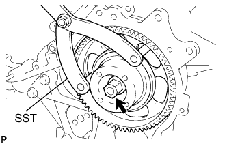
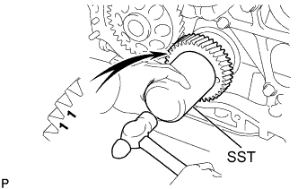
Using SST, torque the nut.
- SST
- 09960-10010 ( 09962-01000, 09963-00600 )
- Torque:
- 64 N*m { 653 kgf*cm, 47 ft.*lbf }
-
-
INSTALL CRANKSHAFT TIMING GEAR OR SPROCKET
-
Align the crankshaft timing gear with timing mark 1 facing the forward.
-
Align the set key on the crankshaft with the key groove of the crankshaft timing gear.
-
Using SST and a hammer, tap in the pulley.
- SST
- 09223-00010
-
-
INSTALL IDLE GEAR SHAFT NO.1
-
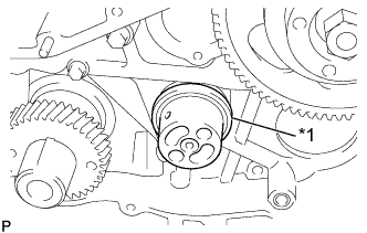
Text in Illustration *1 Idler Gear Shaft Install the idler gear shaft.
-
Coat the idler gear shaft with engine oil.
-
Install the idler gear shaft to the cylinder block.
-
-
-
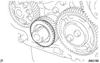
INSTALL IDLE GEAR NO.1
-
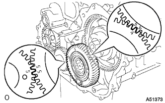
Align the idler gear assembly timing marks "5" and "4" with the crankshaft timing gear mark "5" and injection pump drive gear timing mark "4" respectively, and mesh the gears.
-
-
INSTALL IDLE GEAR THRUST PLATE
-
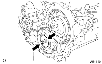
Align the thrust plate set bolt holes.
-
Install the 2 bolts to the idle gear thrust plate.
- Torque:
- 50 N*m { 510 kgf*cm, 37 ft.*lbf }
-
Remove the service bolt.
-
Install the crank position sensor plate.
-
-
INSTALL TIMING GEAR COVER OIL SEAL (Injection Pump)
-
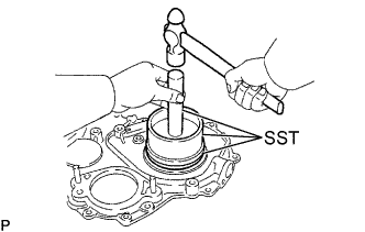
Using SST and a hammer, tap in a new oil seal until its surface is flush with the timing gear cover edge.
- SST
- 09223-15020
- 09502-12010
- 09950-70010 ( 09951-07100 )
-
Apply MP grease to the oil seal lip.
-
-
INSTALL TIMING GEAR COVER OIL SEAL (Crankshaft Front)
-
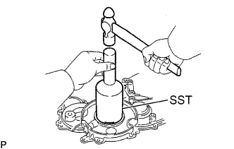
Using SST and a hammer, tap in a new oil seal until its surface is flush with the timing gear cover edge.
- SST
- 09214-76011
-
Apply MP grease to the oil seal lip.
-
-
INSTALL TIMING GEAR CASE
-
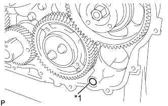
Text in Illustration *1 O-ring Install a new O-ring to the timing gear case.
-
Remove any old packing (FIPG) material and be careful not to drop any oil on the contact surfaces of the timing gear cover and cylinder block.
-
Using a razor blade and gasket scraper, remove all the old packing (FIPG) material from the gasket surfaces and sealing groove.
-
Thoroughly clean all components to remove all the loose material.
-
Using a non-residue solvent, clean both sealing surfaces.
-
-
Text in Illustration *a Width: 2 - 3 mm Apply seal packing to the timing gear cover as shown in the illustration.
Seal packing Toyota Genuine Seal Packing Black, Three Bond 1207B or equivalent
-
Install a nozzle that has been cut to a 2 - 3mm(0.08 - 0.12 in.) opening.
-
Parts must be assembled within 5 minutes of application. Otherwise the material must be removed and reapplied.
-
Immediately remove nozzle from the tube and reinstall cap.
-
-
Install the timing gear cover with the 14 bolts and 2 nuts.
- Torque:
- 13 N*m { 133 kgf*cm, 10 ft.*lbf }
-
-
INSTALL ENGINE OIL LEVEL SENSOR
- Torque:
- 5 N*m { 51 kgf*cm, 44 in.*lbf }
-
INSTALL INJECTION PUMP ASSEMBLY
-
INSTALL CRANK POSITION NO.2 SENSOR
- Torque:
- 8.5 N*m { 87 kgf*cm, 75 in.*lbf }
-
INSTALL CRANK POSITION SENSOR
- Torque:
- 8.5 N*m { 87 kgf*cm, 75 in.*lbf }
-
INSTALL WATER PUMP ASSEMBLY
-
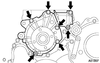
Install a new gasket, and install the water pump, 5 bolts and 2 nuts.
- Torque:
- 13 N*m { 130 kgf*cm, 9 ft.*lbf }
-
-
INSTALL V-RIBBED BELT TENSIONER ASSEMBLY
-
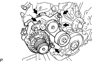
Install the alternator with belt tensioner assembly and 5 bolts.
- Torque:
- 21 N*m { 214 kgf*cm, 15 ft.*lbf }
-
-
INSTALL CRANKSHAFT PULLEY
-
Align the pulley set key with the key groove of the pulley.
-
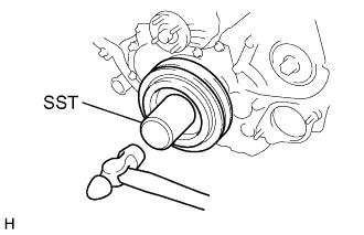
Using SST and a hammer, tap in the pulley.
- SST
- 09214-60010
-
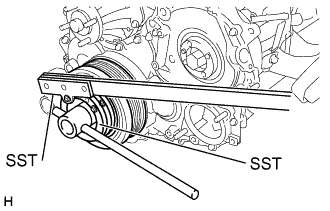
Using SST, install and torque the plate bolt.
- SST
- 09213-58012
- 09330-00021
- Torque:
- 365 N*m { 3,700 kgf*cm, 269 ft.*lbf }
-
-
INSTALL VANE PUMP ASSEMBLY
-
INSTALL VACUUM PUMP ASSEMBLY
-
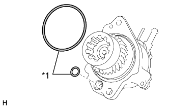
Text in Illustration *1 New O-ring Install 2 new O-rings to the vacuum pump.
-
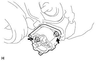
Install the vacuum pump with the 2 nuts.
- Torque:
- 21 N*m { 214 kgf*cm, 15 ft.*lbf }
-
-
INSTALL TIMING BELT COVER NO.2
-
INSTALL CAMSHAFT TIMING PULLEY
-
INSTALL TIMING BELT
-
REPLACE ENGINE OIL
-
CHECK ENGINE OIL LEAK
-
REFILL ENGINE COOLANT
-
CHECK ENGINE COOLANT LEAK
-
REPLACE POWER STEERING FLUID
-
BLEED POWER STEERING FLUID
-
Check the fluid level.
-
Jack up the front of the vehicle and support it with stands.
-
Turn the steering wheel.
-
With the engine stopped, turn the wheel slowly from lock to lock several times.
-
-
Lower the vehicle.
-
Start the engine.
-
Run the engine at idle for a few minutes.
-
-
Turn the steering wheel.
-
With the engine idling, turn the wheel to the left or right full lock position and keep it there for 2 - 3 seconds. Then turn the wheel to the opposite full lock position and keep it there for 2 - 3 seconds (step A).
-
Repeat step A several times.
-
-
Stop the engine.
-
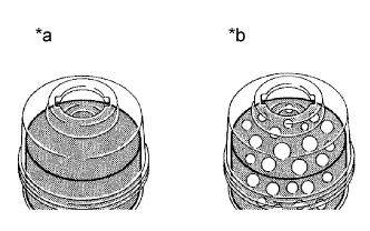
Text in Illustration *a Normal *b Abnormal Check for foaming or emulsification.
Especially, if the system has to be bled twice because of foaming or emulsification, check for fluid leakage in the system.
-
Check the fluid level.
-
-
CHECK POWER STEERING FLUID LEAKAGE