OIL PUMP INSPECTION

-
INSPECT RELIEF VALVE
-
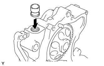
Coat the valve with engine oil and check that it falls smoothly into the valve hole by its own weight.
If it doesn't, replace the relief valve. If necessary, replace the oil pump assembly.
-
-
INSPECT ROTOR
-
Insert the driven rotor into the timing gear case with the mark facing the gear cover side (See step Click here).
-
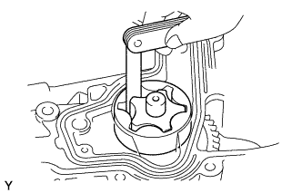
Inspect the rotor tip clearance.
-
Using a feeler gauge, measure the clearance between the drive and driven rotor tips.
Standard tip clearance 0.060 - 0.160 mm (0.0024 - 0.0063 in.) Maximum tip clearance 0.21 mm (0.0083 in.) If the tip clearance is greater than maximum, replace the rotors and gear case as set.
-
-
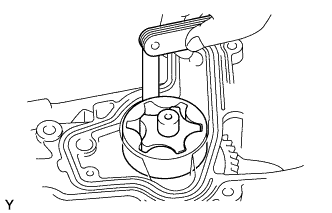
Inspect the rotor body clearance.
-
Using a feeler gauge, measure the clearance between the driven rotor and gear case.
Standard body clearance 0.100 - 0.195 mm (0.0039 - 0.0077 in.) Maximum body clearance 0.20 mm (0.0079 in.) If the body clearance is greater than maximum, replace the rotors and gear case as set.
-
-
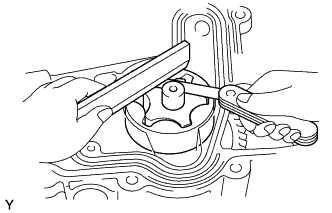
Inspect the rotor side clearance.
-
Using a feeler gauge and precision straight edge, measure the clearance between the rotors and precision straight edge.
Standard side clearance 0.040 - 0.100 mm (0.016 - 0.0039 in.) Maximum side clearance 0.15 mm (0.0059 in.) If the body clearance is greater than maximum, replace the rotors and gear case as set.
-
-