OIL PUMP (w/o DPF) INSTALLATION

-
INSTALL TIMING GEAR CASE ASSEMBLY
-
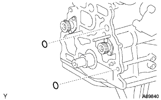
Install 2 new O-rings to the cylinder block grooves.
-
Remove any old packing (FIPG) material.
-
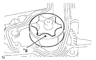
Text in Illustration *a Mark Install the driven rotor into the timing gear case with the mark facing the cylinder block side.
-
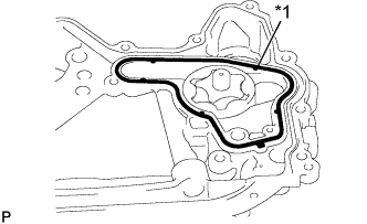
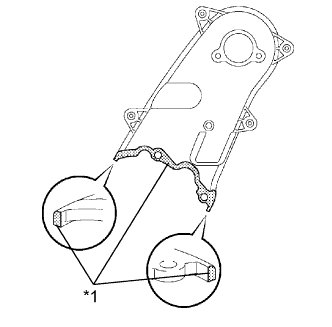
Text in Illustration *1 Gasket Install a new gasket into the groove of the timing gear case.
-
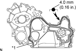
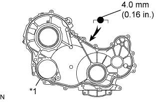
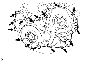
Text in Illustration *1 Seal Packing Apply seal packing to the timing gear case as shown in the illustration.
Seal packing Toyota Genuine Seal Packing Black, Three Bond 1207B or equivalent Standard seal diameter 4.0 mm (0.16 in.) Note
Install the timing gear case within 3 minutes and tighten the bolts within 15 minutes of applying FIPG.
-
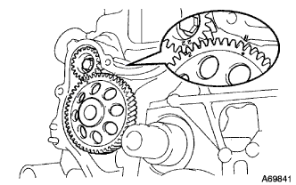
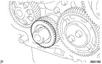
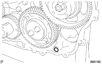
Align the "2" marks of the No. 1 balance shaft driven gear with the oil pump drive gear.
-
Align the mark on the oil pump drive gear with the mark on the timing gear case.
-
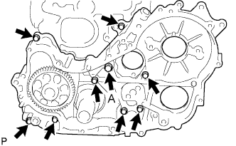
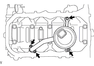
Install the timing gear case with the union bolt and 8 bolts.
- Torque:
- Union Bolt (A)
- 16 N*m { 163 kgf*cm, 12 ft.*lbf }
- Other Bolts
- 13 N*m { 133 kgf*cm, 10 ft.*lbf }
-
Remove the screw plug and gasket.
-
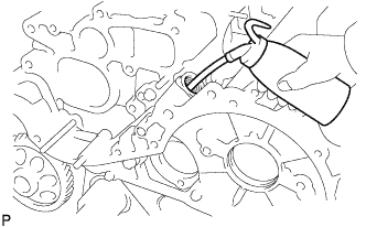
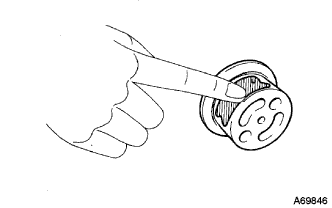
Pour approx. 50 cc (3.05 cu in.) of engine oil into the oil pump.
-
Install a new gasket and screw plug.
- Torque:
- 44 N*m { 449 kgf*cm, 32 ft.*lbf }
-
-
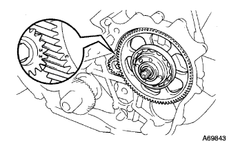
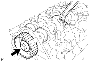
INSTALL CRANKSHAFT TIMING GEAR
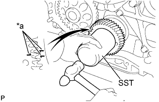
Text in Illustration *a Mark
-
Face the crankshaft timing gear with timing marks "1" forward.
-
Align the set key on the crankshaft with the key groove of the crankshaft timing gear.
-
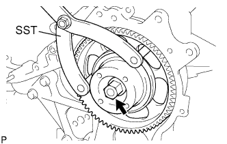
Using SST and a hammer, tap on the crankshaft timing gear.
- SST
- 09223-00010
-
-
INSTALL FUEL SUPPLY PUMP
-
Install a new O-ring to the supply pump.
-
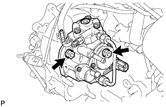
Install the supply pump to the timing gear case with the 2 nuts.
- Torque:
- 21 N*m { 214 kgf*cm, 15 ft.*lbf }
-
-
INSTALL INJECTION GEAR
-
Align the "3" marks of the No. 2 balance shaft driven gear with the injection gear.
-
Install a new O-ring to the injection gear and temporarily tighten the nut.
-
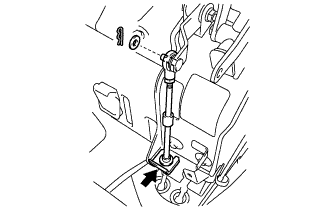
Using SST, hold the injection gear and tighten the nut.
- SST
- 09960-10010 ( 09962-01000, 09963-01000 )
- Torque:
- 64 N*m { 653 kgf*cm, 47 ft.*lbf }
-
-
INSTALL NO. 1 IDLE GEAR SHAFT
-
Coat the No. 1 idle gear shaft with engine oil as shown in the illustration.
-
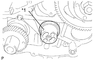
Text in Illustration *1 Oil Hole Install the No. 1 idle gear shaft as shown in the illustration.
-
-
INSTALL IDLE GEAR
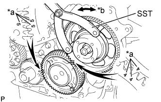
Text in Illustration *a Mark *b Turn
-
Align the "5" marks of the idle gear with the crankshaft timing gear.
-
Using SST, turn the injection gear, and align the "4" marks of the idle gear with the injection gear, and mesh the gears.
- SST
- 09960-10010 ( 09962-01000, 09963-01000 )
-
-
INSTALL IDLE GEAR THRUST PLATE
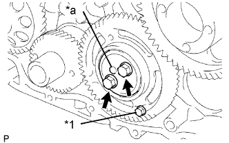
Text in Illustration *1 Service Bolt *a Protrusion
-
Position the thrust plate with the protrusion facing forward.
-
Align the bolt holes, and install the thrust plate with the 2 bolts.
- Torque:
- 50 N*m { 510 kgf*cm, 37 ft.*lbf }
-
Remove the service bolt.
-
-
INSTALL NO. 1 CRANKSHAFT POSITION SENSOR PLATE
-
Align the set key with the key groove of the No. 1 crankshaft position sensor plate.
-
Install the No. 1 crankshaft position sensor plate with the cup side facing outward.
-
-
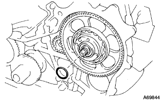
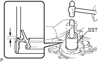
INSTALL TIMING GEAR CASE OR TIMING CHAIN CASE OIL SEAL
-
Using SST and a hammer, tap in a new oil seal until its surface is flush with the timing gear cover edge.
- SST
- 09649-17010
- 09950-70010 ( 09951-07100 )
Oil seal depth from the flat-end surface 0 to 0.5 mm (0 to 0.020 in.) -
Apply MP grease to the oil seal lip.
Note
Keep the lip clean. Prevent dirt and dust from adhering to the oil seal lip.
-
-
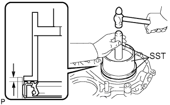
INSTALL TIMING CHAIN OR BELT COVER OIL SEAL
-
Using SST and a hammer, tap in a new oil seal until its surface is flush with the timing gear cover edge.
- SST
- 09608-32010
- 09950-70010 ( 09951-07100 )
Oil seal depth from the flat-end surface 0 to 0.5 mm (0 to 0.020 in.) -
Apply MP grease to the oil seal lip.
Note
Keep the lip clean. Prevent dirt and dust from adhering to the oil seal lip.
-
-
INSTALL TIMING GEAR CASE
-
Remove any old packing (FIPG) material.
-
Text in Illustration *1 Seal Packing Apply seal packing to the timing gear case as shown in the illustration.
Seal packing Toyota Genuine Seal Packing Black, Three Bond 1207B or equivalent Standard seal diameter 4.0 mm (0.16 in.) Note
Install the timing gear case within 3 minutes and tighten the bolts within 15 minutes of applying FIPG.
-
Install a new O-ring to the timing gear case.
-
Install the timing gear case with the 14 bolts and 2 nuts.
- Torque:
- 13 N*m { 133 kgf*cm, 10 ft.*lbf }
-
-
INSTALL OIL STRAINER SUB-ASSEMBLY
-
Install a new gasket and oil strainer with the 2 bolts and 2 nuts.
- Torque:
- 8.0 N*m { 82 kgf*cm, 71 in.*lbf }
-
-
INSTALL OIL PAN SUB-ASSEMBLY (w/ Heater)
Text in Illustration *1 Seal Packing
-
Remove any old packing (FIPG) material.
-
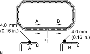
Apply seal packing to the oil pan as shown in the illustration.
Seal packing Toyota Genuine Seal Packing Black, Three Bond 1207B or equivalent Standard seal diameter 4.0 mm (0.16 in.) -
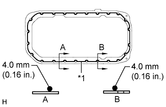
Text in Illustration *1 Seal Packing Apply seal packing to the cylinder block stiffening plate as shown in the illustration.
Seal packing Toyota Genuine Seal Packing Black, Three Bond 1207B or equivalent Standard seal diameter 4.0 mm (0.16 in.) Note
Install the stiffening plate and oil pan within 3 minutes and tighten the bolts within 15 minutes of applying FIPG.
-
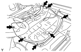
Install the stiffening plate and oil pan with the 22 bolts and 2 nuts.
- Torque:
- 12 N*m { 122 kgf*cm, 9 ft.*lbf }
-
Install the vinyl tube to the oil pan.
-
-
INSTALL OIL PAN SUB-ASSEMBLY (w/o Heater)
Text in Illustration *1 Seal Packing
-
Remove any old packing (FIPG) material.
-
Apply seal packing to the oil pan as shown in the illustration.
Seal packing Toyota Genuine Seal Packing Black, Three Bond 1207B or equivalent Standard seal diameter 4.0 mm (0.16 in.) Note
Install the oil pan within 3 minutes and tighten the bolts within 15 minutes of applying FIPG.
-
Install the oil pan with the 22 bolts and 2 nuts.
- Torque:
- 12 N*m { 122 kgf*cm, 9 ft.*lbf }
-
Install the vinyl tube to the oil pan.
-
-
INSTALL ENGINE OIL LEVEL SENSOR
-
Install a new gasket to the engine oil level sensor.
-
Install the engine oil level sensor with the 4 bolts.
- Torque:
- 7.0 N*m { 71 kgf*cm, 62 in.*lbf }
-
Connect the engine oil level sensor connector.
-
-
INSTALL NO. 2 REAR END PLATE
-
Temporarily install the No. 2 rear end plate to the clutch housing.
-
Insert the No. 4 cylinder block insulator between the No. 2 rear end plate and oil pan.
-
Fully tighten the No. 2 rear end plate with the 4 bolts.
- Torque:
- 73 N*m { 744 kgf*cm, 54 ft.*lbf }
-
-
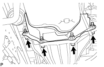
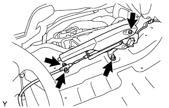
INSTALL FRONT SUSPENSION MEMBER ASSEMBLY
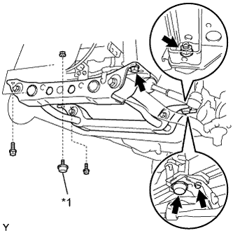
Text in Illustration *1 Front Suspension Damper
-
Temporarily tighten the 4 bolts and install the front suspension member assembly.
-
Temporarily tighten the 2 nuts and 2 suspension dampers.
-
Fully tighten the 4 bolts.
- Torque:
- 150 N*m { 1530 kgf*cm, 111 ft.*lbf }
-
Fully tighten the 2 nuts and 2 suspension dampers.
- Torque:
- 120 N*m { 1224 kgf*cm, 89 ft.*lbf }
-
-
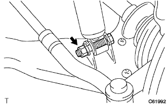
INSTALL PRESSURE FEED TUBE ASSEMBLY
-
Connect the tube with the union bolt and a new gasket.
- Torque:
- 42.1 N*m { 430 kgf*cm, 31 ft.*lbf }
-
-
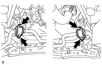
INSTALL STEERING GEAR OUTLET RETURN TUBE
-
Install the return tube.
- Torque:
- 44 N*m { 450 kgf*cm, 33 ft.*lbf }
-
Face the claw to the vehicle is front, and install the return hose to the PS gear assembly with the clip.
-
Install the hose with bolt (LHD steering position type only).
- Torque:
- 18 N*m { 184 kgf*cm, 13 ft.*lbf }
-
-
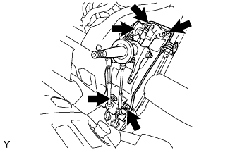
INSTALL STEERING TORQUE SHAFT ASSEMBLY
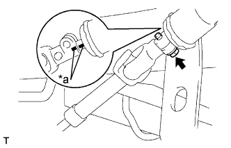
Text in Illustration *a Matchmark
-
Align the matchmarks on the torque shaft and bevel gear.
-
Tighten the bolt.
- Torque:
- 35 N*m { 357 kgf*cm, 26 ft.*lbf }
-
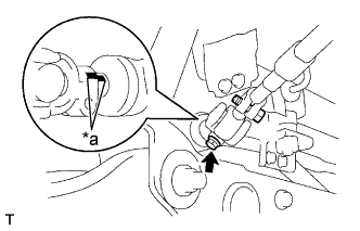
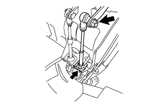
Text in Illustration *a Matchmark Align the matchmarks on the sliding yoke and steering gear.
-
Tighten the bolt.
- Torque:
- 35 N*m { 357 kgf*cm, 26 ft.*lbf }
-
-
INSTALL FRONT LOWER BALL JOINT ASSEMBLY LH
-
Support the front suspension lower arm No. 1 LH with a jack, connect the front suspension lower arm No. 1 LH to the steering knuckle.
-
Install new castle nut to the steering knuckle.
- Torque:
- 140 N*m { 1428 kgf*cm, 103 ft.*lbf }
-
Install new cotter pin.
-
-
INSTALL FRONT LOWER BALL JOINT ASSEMBLY RH
Tech Tips
The installation procedure for the RH side is the same as that for the LH side.
-
INSTALL FRONT STABILIZER BAR
-
Install the 4 bolts and connect the stabilizer bar.
- Torque:
- 36 N*m { 367 kgf*cm, 27 ft.*lbf }
-
-
TEMPORARILY TIGHTEN FRONT SHOCK ABSORBER ASSEMBLY LH
-
Install the front shock absorber assembly LH and bolt, temporarily tighten the nut.
-
-
TEMPORARILY TIGHTEN FRONT SHOCK ABSORBER ASSEMBLY RH
Tech Tips
The installation procedure for the RH side is the same as that for the LH side.
-
INSTALL TIE ROD END SUB-ASSEMBLY LH
-
Connect the tie rod end to the knuckle arm.
-
Install the nuts and new cotter pin.
- Torque:
- 91 N*m { 928 kgf*cm, 67 ft.*lbf }
-
-
INSTALL TIE ROD END SUB-ASSEMBLY RH
Tech Tips
The installation procedure for the RH side is the same as that for the LH side.
-
INSTALL CRANKSHAFT PULLEY
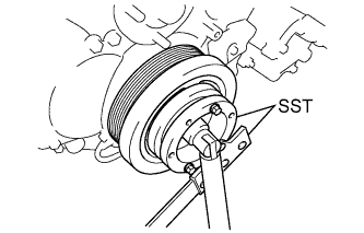
-
Using SST, hold the crankshaft pulley and tighten the bolt.
- SST
- 09213-58013
- 09330-00021
- Torque:
- 365 N*m { 3722 kgf*cm, 269 ft.*lbf }
-
-
INSTALL CAMSHAFT POSITION SENSOR
-
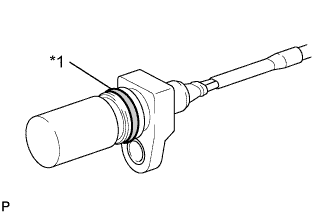
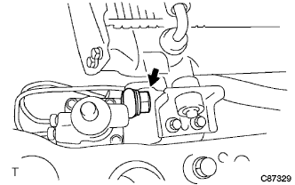
Text in Illustration *1 O-ring Apply a light coat of engine oil to the O-ring on the crankshaft position sensor.
-
Install the crankshaft position sensor with the bolt.
- Torque:
- 8.5 N*m { 87 kgf*cm, 75 in.*lbf }
Note
Be careful that the O-ring is not cracked or jammed when installing the crankshaft position sensor.
-
Attach the 3 wire harness clamps.
-
Connect the crankshaft position sensor connector.
-
-
INSTALL CRANKSHAFT POSITION SENSOR
-
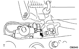
Text in Illustration *1 O-ring Apply a light coat of engine oil to the O-ring on the crankshaft position sensor.
-
Install the crankshaft position sensor with the bolt.
- Torque:
- 8.5 N*m { 87 kgf*cm, 75 in.*lbf }
Note
Be careful that the O-ring is not cracked or jammed when installing the crankshaft position sensor.
-
Attach the 3 wire harness clamps.
-
Connect the crankshaft position sensor connector.
-
-
INSTALL PUMP DRIVE SHAFT PULLEY
-
Install camshaft timing pulley flange No. 2 and pump drive shaft pulley with the 4 bolts.
- Torque:
- 31 N*m { 316 kgf*cm, 23 ft.*lbf }
-
-
INSTALL MANIFOLD STAY
-
Install the manifold stay with the 2 bolts.
- Torque:
- 19 N*m { 194 kgf*cm, 14 ft.*lbf }
-
Connect the wire harness to the manifold stay.
-
-
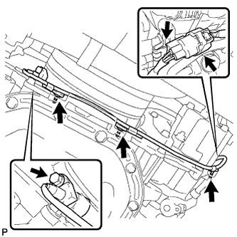
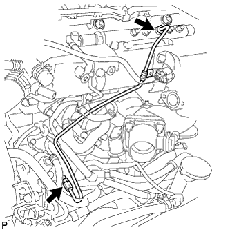
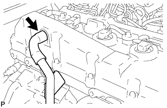
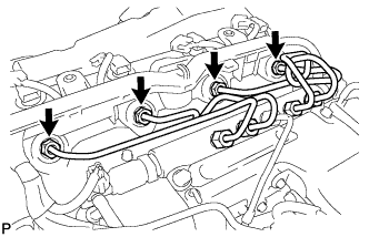
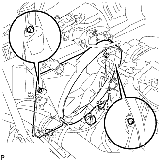
INSTALL FUEL INLET PIPE SUB-ASSEMBLY
Note
When replacing the fuel supply pump, common rail, cylinder block, cylinder head, cylinder head gasket, or timing gear case with a new one, replace the fuel inlet pipe sub-assembly.
-
Temporarily install the fuel inlet pipe sub-assembly.
-
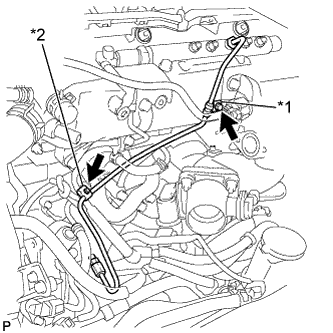
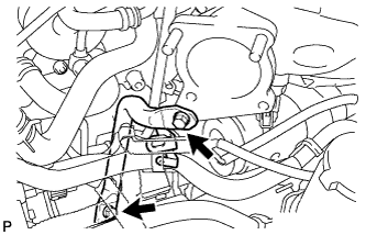
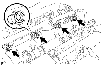
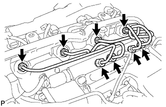
Text in Illustration *1 No. 1 Clamp *2 No. 2 Clamp Connect the No. 1 injection pipe clamp with the bolt.
- Torque:
- 5.0 N*m { 51 kgf*cm, 44 in.*lbf }
-
Install the No. 2 injection pipe clamp with the bolt.
- Torque:
- 5.0 N*m { 51 kgf*cm, 44 in.*lbf }
-
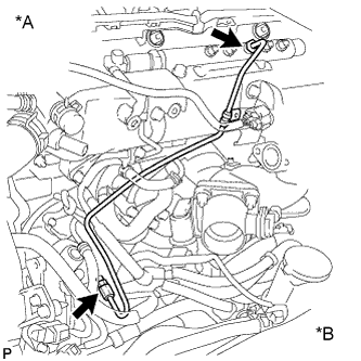
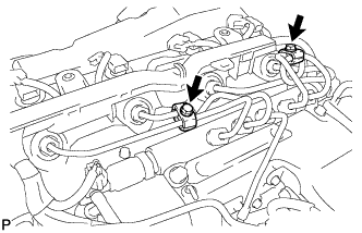
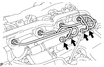
Text in Illustration *A Common Rail Side *B Supply Pump Side Using union nut wrench 17mm, tighten the union nut on the common rail side to the specified torque.
- Torque:
- 35 N*m { 357 kgf*cm, 26 ft.*lbf }
Note
Use the formula to calculate special torque values for situations where a union nut wrench is combined with a torque wrench Click here.
-
Using union nut wrench 17 mm, tighten the union nut on the supply pump to the specified torque.
- Torque:
- 35 N*m { 357 kgf*cm, 26 ft.*lbf }
Note
Use the formula to calculate special torque values for situations where a union nut wrench is combined with a torque wrench Click here.
-
-
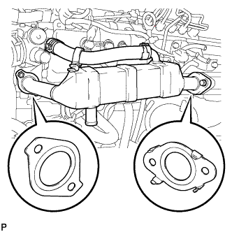
INSTALL EGR COOLER ASSEMBLY (w/ Heater)
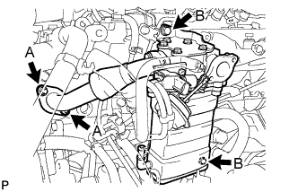
-
Install a new gasket and EGR cooler assembly with the 2 bolts and 2 nuts.
- Torque:
- 13 N*m { 133 kgf*cm, 10 ft.*lbf, for bolt A }
- 20 N*m { 204 kgf*cm, 15 ft.*lbf, for nut B }
-
-
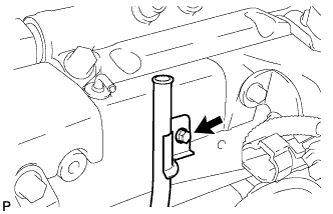
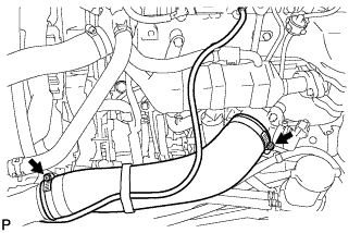
CONNECT NO.3 WATER BY-PASS HOSE (w/ Heater)
-

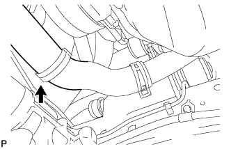
Text in Illustration *a Front *b LH Connect the No. 3 water by-pass hose with the clamp as shown in the illustration.
-
-
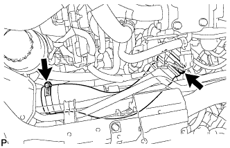
CONNECT WATER BY-PASS HOSE (w/ Heater)

Text in Illustration *a Front *b Upper *c LH
-
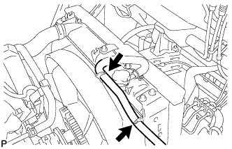
Connect the water by-pass hose with the 2 clamps as shown in the illustration.
-
-
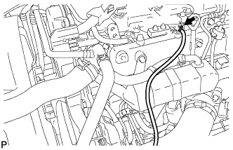
CONNECT NO.4 VACUUM TRANSMITTING HOSE ASSEMBLY (w/ Heater)
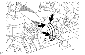
-
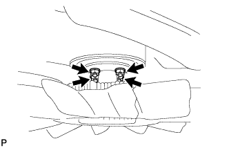
Connect the No. 4 vacuum transmitting hoses assembly as shown in the illustration.
-
-
INSTALL ELECTRIC EGR CONTROL VALVE ASSEMBLY (w/ Heater)
-
Connect the vacuum hose.
-
Install 3 new gaskets and electric EGR control valve with intake air connector with the 3 bolts and 2 nuts.
- Torque:
- 20 N*m { 204 kgf*cm, 15 ft.*lbf }
-
Install the vacuum regulating valve with bracket with the 2 bolts.
- Torque:
- 20 N*m { 204 kgf*cm, 15 ft.*lbf }
-
Connect the 2 vacuum hoses to the vacuum regulating valve.
-
Connect the vacuum regulating valve connector.
-
-
INSTALL MANIFOLD STAY (w/ Heater)
-
Install the manifold stay with the 2 bolts.
- Torque:
- 19 N*m { 194 kgf*cm, 14 ft.*lbf }
-
Attach the wire harness.
-
-
INSTALL ENGINE ROOM MAIN WIRE (w/ Heater)
-
Connect the vacuum hose.
-
Connect the connector.
-
Install the wire harness clamp with bolt.
-
Attach the wire harness clamp.
-
Attach the 2 wire harness clamps.
-
Connect the EGR control valve connector.
-
-
INSTALL NO.1 GAS FILTER (w/ Heater)
-
Install the gas filter with the bolt.
- Torque:
- 5.0 N*m { 51 kgf*cm, 44 in.*lbf }
-
-
INSTALL DIESEL THROTTLE BODY ASSEMBLY (w/ Heater)
-
Install a new gasket and diesel throttle body assembly with the 2 bolts and 2 nuts.
- Torque:
- 20 N*m { 204 kgf*cm, 15 ft.*lbf }
-
Connect the 2 diesel throttle body assembly connectors.
-
Connect the intake air temperature sensor connector.
-
Install the wire harness clamp with the bolt.
-
Attach the wire harness clamp.
-
Connect the turbo pressure sensor connector and No. 1 vacuum switching valve assembly connector.
-
-
INSTALL NO.4 AIR INJECTION SYSTEM HOSE (w/ Heater)
-
Install the No. 4 air air injection system hose and secure the hose clamps as shown in the illustration.
-
-
INSTALL OIL LEVEL GAGE GUIDE (w/o Heater)
-
Apply a small amount of engine oil to a new O-ring and install it to the oil level gage guide.
-
Install the oil level gage guide with the bolt.
- Torque:
- 8.0 N*m { 82 kgf*cm, 71 in.*lbf }
-
Install the oil level gage sub-assembly.
-
-
TEMPORARILY TIGHTEN EGR COOLER ASSEMBLY (w/o Heater)
-
Temporarily install the EGR cooler assembly.
-
Temporarily install the EGR cooler assembly with 2 new gaskets with the 2 bolts and 2 nuts.
-
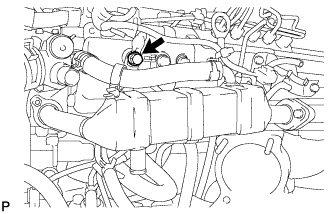
Temporarily install the bolt as shown in the illustration.
-
Tighten the 2 bolts and 2 nuts to the specified torque.
- Torque:
- 13 N*m { 133 kgf*cm, 10 ft.*lbf }
-
-
-
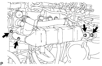
TIGHTEN EGR COOLER ASSEMBLY (w/o Heater)
-
Tighten the EGR cooler assembly.
-
Tighten the bolt to the specified torque.
- Torque:
- 22 N*m { 224 kgf*cm, 16 ft.*lbf }
-
-
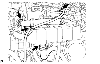
Install the water by-pass hose No. 2 with the clamp.
-
Install the water by-pass hose No. 4 with the clamp.
-
Install the oil return hose with the clamp.
-
-
INSTALL DIESEL THROTTLE BODY (w/o Heater)
-
Install a new gasket to intake air connector.
-
Install the diesel throttle body with the 2 bolts and the 2 nuts.
- Torque:
- 20 N*m { 204 kgf*cm, 15 ft.*lbf }
-
Connect the 2 connectors.
-
-
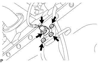
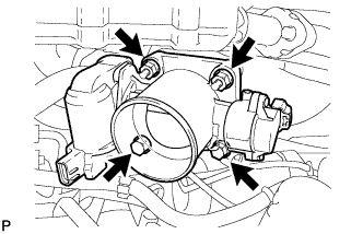
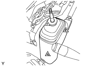
INSTALL VACUUM PUMP
-
Apply engine oil to 2 new O-rings.
-
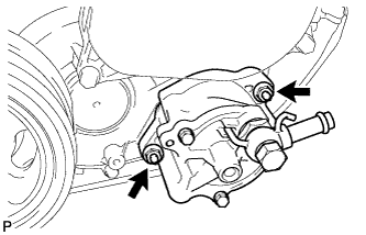
Install the 2 O-rings and the vacuum pump with the 2 nuts.
- Torque:
- 21 N*m { 210 kgf*cm, 15 ft.*lbf }
-
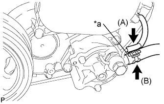
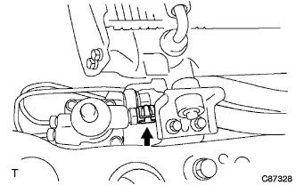
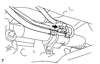
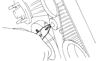
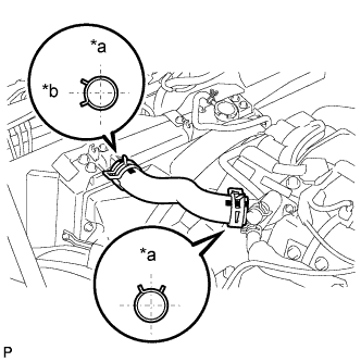
Text in Illustration *a Paint Mark Connect the vacuum hose (A) to the vacuum pump union.
-
Connect the vacuum hose (B) to the vacuum pump union with the clip.
Note
Set the vacuum hose so that the paint mark faces upward.
-
-
INSTALL TIMING GEAR COVER INSULATOR
-
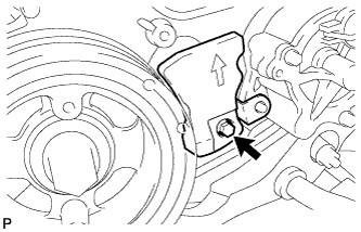
Install the timing gear cover insulator with the bolt.
- Torque:
- 13 N*m { 133 kgf*cm, 10 ft.*lbf }
-
-
INSTALL VANE PUMP
-
Install a new O-ring to the vane pump.
-
Install the vane pump with the 2 nuts.
- Torque:
- 40 N*m { 408 kgf*cm, 30 ft.*lbf }
-
-
INSTALL VANE PUMP OIL RESERVOIR ASSEMBLY
-
Install the vane pump oil reservoir with the 2 bolts.
- Torque:
- 18 N*m { 184 kgf*cm, 13 ft.*lbf }
-
-
INSTALL NO. 3 AIR HOSE
-
Connect the No. 3 air hose with the 2 lamps.
-
Connect the vacuum hose with the clip.
-
-
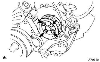
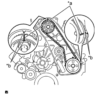
INSTALL WATER PUMP
-
Temporarily install a new gasket and the water pump assembly without cover to the water pump cover with the bolt.
-
Temporarily install a new gasket and the engine water pump assembly to the cylinder block sub-assembly with the 2 nuts and 5 bolts.
-
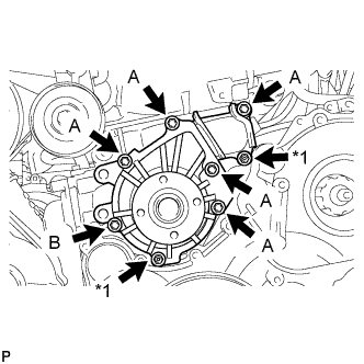
Text in Illustration *1 Nut Fully tighten the 5 bolts A and the 2 nuts.
- Torque:
- 13 N*m { 133 kgf*cm, 10 ft.*lbf }
-
Fully tighten the bolt B.
- Torque:
- 9.1 N*m { 93 kgf*cm, 81 in.*lbf }
-
-
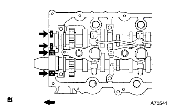
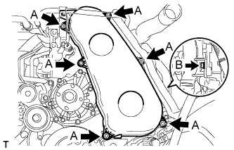
INSTALL NO. 2 TIMING BELT COVER
-
Text in Illustration *1 Seal Packing Apply seal packing (FIPG) to the specified areas shown in the illustration.
Seal packing Toyota Genuine Seal Packing Black, Three Bond 1207B or equivalent Note
After applying FIPG, install the No. 2 timing belt cover within 3 minutes and tighten the bolts and nut within 15 minutes.
-
Install the No. 2 timing belt cover with the 4 bolts and nut.
- Torque:
- 10 N*m { 102 kgf*cm, 7 ft.*lbf }
-
-
INSTALL CAMSHAFT TIMING PULLEY
-
Install the camshaft timing pulley.
-
Fasten the bolt of the camshaft timing pulley while holding the camshaft with a wrench.
- Torque:
- 98 N*m { 999 kgf*cm, 72 ft.*lbf }
-
-
INSTALL CYLINDER HEAD COVER SUB-ASSEMBLY
-
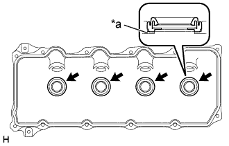
Text in Illustration *a Upper Side of Cylinder Head Cover Sub-assembly Install 4 new No. 3 cylinder head cover gaskets to the cylinder head cover sub-assembly as shown in the illustration.
Note
-
Do not install the gaskets at an angle.
-
Keep the lip of the gasket free from foreign materials.
-
-
Install a new cylinder head cover gasket to the cylinder head cover sub-assembly.
-
Apply a seal packing to the cylinder head as shown in the illustration.
Seal packing Toyota Genuine Seal Packing Black, Three Bond 1207B or equivalent Note
-
Remove any old oil from the contact surface.
-
If the cylinder head cover gasket is cracked or damaged, replace it with a new one.
-
Assemble parts within 3 minutes and tighten them within 15 minutes of applying the seal packing.
-
-
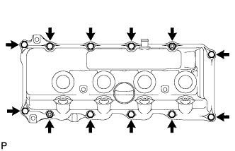
Install the cylinder head cover sub-assembly with 10 bolts and 2 nuts.
- Torque:
- 9.0 N*m { 92 kgf*cm, 80 in.*lbf }
-
Connect the ventilation hose.
-
Install 4 new nozzle holder seals to the cylinder head cover sub-assembly.
-
-
INSTALL INJECTION PIPE SUB-ASSEMBLY
Note
When replacing the fuel injector, common rail, or cylinder head with a new one, replace injection pipe sub-assemblies No. 1, No. 2, No. 3 and No. 4.
-
Temporarily install the injection pipe sub-assembly.
-
Install the 2 injection pipe clamp No. 2 with the 2 bolts.
- Torque:
- 5.0 N*m { 51 kgf*cm, 44 in.*lbf }
-
Using union nut wrench 17 mm, tighten the union nut on the fuel injector side to the specified torque.
- Torque:
- 35 N*m { 357 kgf*cm, 26 ft.*lbf }
Note
Use the formula to calculate special torque values for situations where a union nut wrench is combined with a torque wrench Click here.
-
Using union nut wrench 17 mm, tighten the union nut on the common rail side to the specified torque.
- Torque:
- 35 N*m { 357 kgf*cm, 26 ft.*lbf }
Note
Refer to the torque above when not using SST. When using SST, calculate the torque in accordance with the lengths of SST and the torque wrench Click here.
-
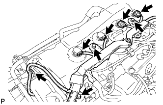
Install the wire harness with the 3 bolts.
- Torque:
- 8.0 N*m { 82 kgf*cm, 71 in.*lbf }
-
Connect the fuel injector connector and harness clamp.
-
-
INSTALL V-RIBBED BELT TENSIONER ASSEMBLY
-
Install the belt tensioner with the 4 bolts.
- Torque:
- 21 N*m { 214 kgf*cm, 16 ft.*lbf }
-
-
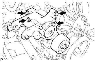
INSTALL GENERATOR
-
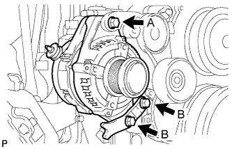
Temporarily install the generator and generator bracket with the 3 bolts.
-
Tighten the 3 bolts to the specified torque.
- Torque:
- 62 N*m { 632 kgf*cm, 46 ft.*lbf, for bolt A }
- 36 N*m { 367 kgf*cm, 27 ft.*lbf, for bolt B }
-
Install the wire harness with the nut to terminal B.
- Torque:
- 9.8 N*m { 100 kgf*cm, 7 ft.*lbf }
-
Install the terminal cap.
-
Connect the generator connector.
-
Apply a small amount of engine oil to a new O-ring and install it to the oil level gage guide.
-
Install the oil level gage guide with the bolt (for LHD).
- Torque:
- 8.0 N*m { 82 kgf*cm, 71 in.*lbf }
-
Install the oil level gage sub-assembly (for LHD).
-
Install the engine wire harness with the 2 bolts and connect the connector (for LHD).
- Torque:
- 8.0 N*m { 82 kgf*cm, 71 in.*lbf }
-
Install the engine wire harness with the 2 bolts and connect the connector (for RHD).
- Torque:
- 8.0 N*m { 82 kgf*cm, 71 in.*lbf }
-
-
INSTALL NO. 1 AIR HOSE
-
Connect the No. 1 air hose and tighten the hose clamp.
-
-
INSTALL NO. 1 TIMING BELT IDLER SUB-ASSEMBLY
-
Using a 10 mm hexagon wrench, install a new washer and the timing belt idler with the bolt.
- Torque:
- 35 N*m { 357 kgf*cm, 26 ft.*lbf }
Note
Do not reuse the washer.
-
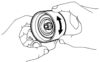
Check that the idler pulley moves smoothly by hand.
If it does not move smoothly, check the idler sub-assembly and washer.
-
-
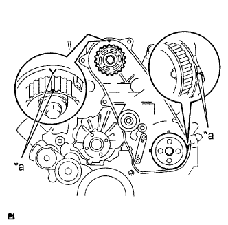
INSTALL TIMING BELT
-
Check that the timing marks are aligned as shown in the illustration.
Text in Illustration *a Timing Marks Tech Tips
If reusing the timing belt, align the points marked during removal, and install the belt with the direction arrow pointing in the direction of engine revolution.
Note
-
The engine should be cold.
-
When turning the crankshaft, the valve heads will hit against the piston's top position. Do not turn it more than necessary.
-
-
Install the timing belt to the pump drive shaft pulley, camshaft timing pulley and No. 1 timing belt idler in sequence.
-
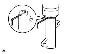
Place the tensioner upright. Then set the press to the top of the tensioner.
Note
-
Do not scratch or deform the rod end.
-
Press in the tensioner rod upward.
-
Protect the tip of the push rod with a cloth in order to prevent damage.
-
-
Using a press, slowly push in the push rod using 981 to 9807 N (100 to 1000 kgf, 220 to 2205 lbf) of force.
Note
Do not impose a load of over 9807 N (1000 kgf, 2205 lbf) to the push rod.
-
Align the holes of the push rod and housing. Then pass a 1.27 mm hexagon wrench through the holes to keep the setting position of the push rod.
-
Install the timing belt tensioner with the 2 bolts while pushing the idler pulley toward the timing belt.
-
Tighten the 2 bolts.
- Torque:
- 13 N*m { 133 kgf*cm, 10 ft.*lbf }
Note
Uniformly tighten the bolts in order to avoid malfunction of the timing belt tensioner.
-
Remove the 1.27 mm hexagon wrench from the tensioner.
-
Text in Illustration *a Matchmarks *b Timing Marks Turn the crankshaft clockwise 720° and check that the timing marks are aligned as shown in the illustration.
-
-
INSTALL NO. 1 TIMING BELT COVER
-
Install the timing belt cover with the 6 bolts (A).
- Torque:
- 6.0 N*m { 61 kgf*cm, 53 in.*lbf }
-
Install the wire harness clamp.
-
Install the water hose clamp with the bolt (B).
- Torque:
- 18 N*m { 184 kgf*cm, 13 ft.*lbf }
-
-
INSTALL FAN PULLEY
-
Install the fan pulley onto the water pump.
-
-
INSTALL FAN SHROUD
-
Temporarily install the fan shroud together with the fan with fluid coupling.
-
Install the fan shroud with the 2 bolts.
- Torque:
- 7.0 N*m { 71 kgf*cm, 62 in.*lbf }
-
Connect the outlet radiator hose onto the fan shroud.
-
Connect the reserve tank hose onto the fan shroud.
-
-
INSTALL FLUID COUPLING ASSEMBLY
-
Temporarily tighten the fluid coupling with the 4 nuts.
-
Install the fan and generator V belt Click here.
-
Fully tighten the 4 nuts.
- Torque:
- 23 N*m { 235 kgf*cm, 17 ft.*lbf }
-
-
INSTALL INLET RADIATOR HOSE
Text in Illustration *a Upper *b Left
-
Install the inlet radiator hose, as shown in the illustration, with the 2 hose clamps.
-
-
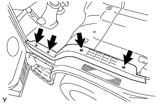
INSTALL ENGINE SIDE COVER SUB-ASSEMBLY LH
-
for Double Cab:
Install the engine side cover LH with the 4 bolts.
- Torque:
- 12 N*m { 122 kgf*cm, 9 ft.*lbf }
-
for Single Cab:
Install the engine side cover LH with the 3 bolts.
- Torque:
- 12 N*m { 122 kgf*cm, 9 ft.*lbf }
-
-
INSTALL ENGINE SIDE COVER SUB-ASSEMBLY RH
-
for Double Cab:
Install the engine side cover RH with the 4 bolts.
- Torque:
- 12 N*m { 122 kgf*cm, 9 ft.*lbf }
-
for Single Cab:
Install the engine side cover RH with the 3 bolts.
- Torque:
- 12 N*m { 122 kgf*cm, 9 ft.*lbf }
-
-
INSTALL ENGINE SERVICE HOLE SUB COVER SUB-ASSEMBLY (for Double Cab)
-
Install the engine service hole sub cover with the 7 bolts.
- Torque:
- 12 N*m { 120 kgf*cm, 9 ft.*lbf }
-
-
INSTALL PARKING BRAKE LEVER ASSEMBLY (for Double Cab)
-
Install the parking brake lever with the 4 bolts.
- Torque:
- 17 N*m { 175 kgf*cm, 13 ft.*lbf }
-
Connect the connector.
-
-
INSTALL TRANSMISSION FLOOR SHIFT ASSEMBLY (for Double Cab)
-
Install the transmission floor shift with the 4 bolts.
- Torque:
- 18 N*m { 185 kgf*cm, 13 ft.*lbf }
-
-
INSTALL FLOOR SHIFT CABLE TRANSMISSION CONTROL SHIFT (for Double Cab)
-
Install the floor shift cable transmission control shift with the nut and washer.
- Torque:
- 12 N*m { 120 kgf*cm, 9 ft.*lbf }
-
Install a new clip.
-
-
INSTALL FLOOR SHIFT CABLE TRANSMISSION CONTROL SELECT (for Double Cab)
-
Install the floor shift cable transmission control select with clip and washer.
-
Install a new clip.
-
-
INSTALL NO. 1 FRONT FLOOR MAT REAR (for Double Cab)
-
INSTALL FRONT FLOOR PANEL BRACE (for Double Cab)
-
Install the front floor panel brace with the 3 clips.
-
-
INSTALL SHIFT LEVER KNOB SUB-ASSEMBLY (for Double Cab)
-
INSTALL PARKING BRAKE HOLE COVER (for Double Cab)

-
Install the parking brake hole cover with the screw.
-
-
INSTALL FRONT DOOR SCUFF PLATE LH (for Double Cab)
-
Install the front door scuff plate LH with the 4 screws.
-
-
INSTALL FRONT SEAT ASSEMBLY LH (for Double Cab)
-
Install the front seat LH with the 4 bolts.
- Torque:
- 39 N*m { 400 kgf*cm, 29 ft.*lbf }
-
Connect the connector.
-
-
INSTALL FRONT WHEEL
- Torque:
- for Full Just Low
- 365 N*m { 3722 kgf*cm, 269 ft.*lbf }
- for except Full Just Low
- 135 N*m { 1377 kgf*cm, 100 ft.*lbf }
-
STABILIZE SUSPENSION
-
Bounce the vehicle up and down several times to stabilize the suspension.
-
-
FULLY TIGHTEN FRONT SHOCK ABSORBER ASSEMBLY LH
-
Fully tighten the nut.
- Torque:
- 105 N*m { 1071 kgf*cm, 77 ft.*lbf }
-
-
FULLY TIGHTEN FRONT SHOCK ABSORBER ASSEMBLY RH
Tech Tips
The installation procedure for the RH side is the same as that for the LH side.
-
CONNECT CABLE TO NEGATIVE BATTERY TERMINAL
- Torque:
- 6.4 N*m { 65 kgf*cm, 57 in.*lbf }
-
ADD POWER STEERING FLUID
-
BLEED POWER STEERING FLUID
-
ADD ENGINE OIL
-
Add fresh oil and install the oil filler cap.
Engine oil Oil Grade Oil Viscosity (SAE)
-
API CF-4 or CF, G-DLD-1, ACEA B1
-
20W-50
-
15W-40
-
10W-30
-
5W-30 Preferred
Capacity Item Fill Amount Drain and refill with oil filter change 7.0 liters (7.4 US qts, 6.2 lmp. qts) Drain and refill without oil filter change 6.8 liters (7.2 US qts, 6.0 lmp. qts) Dry fill 7.7 liters (8.1 US qts, 6.8 lmp. qts) -
-
-
BLEED AIR FROM FUEL SYSTEM
-
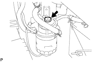
Using the hand pump, bleed air from the fuel system until pumping becomes difficult.
-
-
ADD ENGINE COOLANT
-
Pour coolant into the radiator until it overflows.
Capacity Specification Capacity w/o Heater 9.8 liters (10.3 US qts, 8.6 Imp. qts) w/ Front Heater 10.7 liters (11.3 US qts, 9.4 Imp. qts) w/ Front and Rear Heater 11.5 liters (12.2 US qts, 10.1 Imp. qts) Note
Do not substitute plain water for engine coolant.
Tech Tips
-
Use of improper coolants may damage the engine cooling system.
-
Use only Toyota Super Long Life Coolant or similar high quality ethylene glycol based non-silicate, non-amine, non-nitrite, and non-borate coolant with long-life hybrid organic acid technology (coolant with long-life hybrid organic acid technology consists of a combination of low phosphates and organic acids).
-
-
Check the coolant level inside the radiator by squeezing the inlet and outlet radiator hoses several times by hand.
If the coolant level goes down, add coolant.
-
Install the radiator cap securely.
-
Slowly pour coolant into the radiator reservoir until it reaches the FULL line.
-
Warm up the engine until the thermostat opens.
-
While the thermostat is open, circulate the coolant for several minutes.
Tech Tips
The thermostat open timing can be confirmed by pressing the inlet radiator hose by hand, and checking when the engine coolant starts to flow inside the hose.
-
-
Maintain the engine speed at 2000 to 2500 rpm.
-
Squeeze the inlet and outlet radiator hoses several times by hand while warming up the engine to bleed the air.
CAUTION:
-
Wear protective gloves.
-
Be careful as the radiator hoses are hot.
-
Keep your hands away from the fan.
When squeezing the radiator hoses:
-
-
Stop the engine and wait until the coolant cools down.
-
Remove the radiator cap and check the coolant level inside the radiator.
-
If the coolant level is below the full level, repeat the operation until the coolant level remains at the full level.
-
Check the coolant level inside the radiator reservoir tank again.
If it is below the full level, add coolant.
-
-
INSPECT FOR FLUID LEAK
-
INSPECT FOR OIL LEAK
-
Warm up the engine and inspect for oil leak.
-
-
INSPECT FOR FUEL LEAK
-
PERFORM ACTIVE TEST
-
Connect the intelligent tester to the DLC3.
-
Turn the ignition switch ON.
-
Turn the intelligent tester ON.
-
Start the engine.
-
Enter the following menus: Powertrain / ECD / Active Test.
-
Perform the Active Test.
Intelligent Tester Display Test Details Control Range Diagnostic Notes Test the Fuel Leak Pressurizes common rail internal fuel pressure, and checks for fuel leaks Stop/Start
-
Fuel pressure inside common rail pressurized to specified value and engine speed increased to 2,000 rpm when ON is selected
-
Above conditions preserved while test is ON
-
-
Make sure that there is no fuel leakage in the fuel system during the Active Test.
-
-
-
INSPECT FOR COOLANT LEAK
-
Remove the radiator cap.
CAUTION:
To avoid the danger of being burned, do not remove the radiator cap while the engine and radiator are still hot. Thermal expansion will cause hot engine coolant and steam to blow out from the radiator.
-
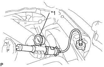
Text in Illustration *1 Radiator Cap Tester Fill the radiator with coolant and attach a radiator cap tester.
-
Warm up the engine.
-
Pump it to 118 kPa (1.2 kgf/cm2, 17.1 psi), then check that the pressure does not drop.
If the pressure drops, check the hoses, radiator and water pump for leakage. If there are no signs of external coolant leakage, check the heater core, cylinder block and head.
-
Reinstall the radiator cap.
-
-
INSPECT AND ADJUST FRONT WHEEL ALIGNMENT