OIL PUMP (w/o DPF) REMOVAL

-
DISCONNECT CABLE FROM NEGATIVE BATTERY TERMINAL
-
REMOVE FRONT WHEEL
-
DRAIN ENGINE COOLANT
CAUTION:
To avoid the danger of being burned, do not remove the radiator cap while the engine and radiator are still hot. Thermal expansion will cause hot engine coolant and steam to blow out from the radiator.
-
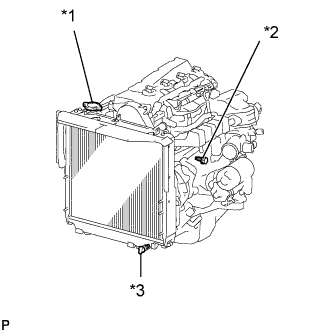
Text in Illustration *1 Radiator Cap *2 Engine Drain Plug *3 Radiator Drain Plug Loosen the radiator drain plug (on the radiator).
-
Remove the radiator cap.
-
Loosen the engine drain plug (on the oil cooler cover), and drain the coolant.
-
Drain the coolant from the reservoir tank.
-
Tighten the engine drain plug.
- Torque:
- 8.0 N*m { 82 kgf*cm, 71 in.*lbf }
-
-
DRAIN ENGINE OIL
-
Remove the oil filler cap.
-
Remove the drain plug from the oil pan and drain the engine oil into a container.
-
Clean the drain plug.
-
Install the drain plug with a new gasket.
- Torque:
- 34 N*m { 347 kgf*cm, 25 ft.*lbf }
-
-
REMOVE FRONT SEAT ASSEMBLY LH (for Double Cab)
-
Disconnect the connector.
-
Remove the 4 bolts and front seat LH.
-
-
REMOVE FRONT DOOR SCUFF PLATE LH (for Double Cab)
-
Remove the 4 screws and front door scuff plate LH.
-
-
REMOVE PARKING BRAKE HOLE COVER (for Double Cab)

-
Remove the screw and parking brake hole cover.
-
-
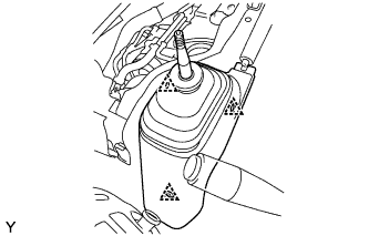
REMOVE SHIFT LEVER KNOB SUB-ASSEMBLY (for Double Cab)
-
REMOVE FRONT FLOOR PANEL BRACE (for Double Cab)
-
Remove the 3 clips, then remove the floor panel brace with the shifting hole cover.
-
-
REMOVE NO. 1 FRONT FLOOR MAT REAR (for Double Cab)
-
SEPARATE FLOOR SHIFT CABLE TRANSMISSION CONTROL SELECT (for Double Cab)
-
Remove the clip.
-
Remove the clip and washer, and separate the floor shift cable transmission control select.
-
-
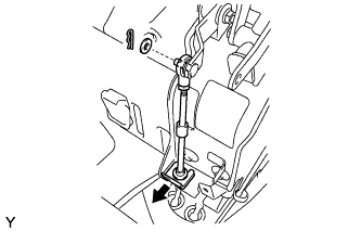
SEPARATE FLOOR SHIFT CABLE TRANSMISSION CONTROL SHIFT (for Double Cab)
-

Remove the clip.
-
Remove the nut and washer, and separate the floor shift cable transmission control shift.
-
-
REMOVE TRANSMISSION FLOOR SHIFT ASSEMBLY (for Double Cab)
-
Remove the 4 bolts and transmission floor shift.
-
-
SEPARATE PARKING BRAKE LEVER ASSEMBLY (for Double Cab)
-
Disconnect the connector.
-
Remove the 4 bolts, and separate the parking brake lever with parking brake cable.
-
-
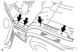
REMOVE ENGINE SERVICE HOLE SUB COVER SUB-ASSEMBLY (for Double Cab)
-
Remove the 7 bolts and engine service hole sub cover.
-
-
REMOVE ENGINE SIDE COVER SUB-ASSEMBLY LH
-
for Single Cab:
Remove the 4 bolts and engine side cover LH.
-
for Double Cab:
Remove the 3 bolts and engine side cover LH.
-
-
REMOVE ENGINE SIDE COVER SUB-ASSEMBLY RH
-
for Single Cab:
Remove the 4 bolts and engine side cover RH.
-
for Double Cab:
Remove the 3 bolts and engine side cover RH.
-
-
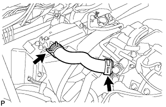
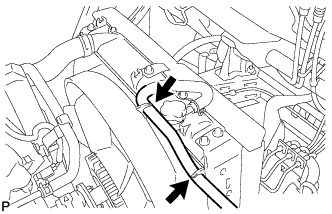
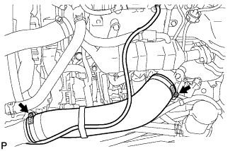
REMOVE INLET RADIATOR HOSE
-
Disconnect the 2 hose clamps and remove the inlet radiator hose.
-
-
REMOVE FLUID COUPLING ASSEMBLY
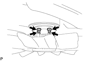
-
Loosen the 4 nuts from the fan pulley.
-
Remove the fan and generator V belt Click here.
-
Remove the 4 nuts.
-
-
REMOVE FAN SHROUD
-
Disconnect the reserve tank hose from the fan shroud.
-
Disconnect the outlet radiator hose from the fan shroud.
-
Remove the 2 bolts and separate the the fan shroud.
-
Remove the fan with fluid coupling and fan shroud.
-
-
REMOVE FAN PULLEY
-
Remove the fan pulley from the water pump.
-
-
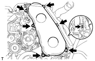
REMOVE NO. 1 TIMING BELT COVER
-
Remove the bolt and water hose clamp.
-
Remove the wire harness clamp.
-
Remove the 6 bolts and timing belt cover.
-
-
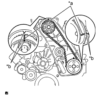
REMOVE TIMING BELT
-
Set No. 1 cylinder to TDC/compression.
-
Turn the crankshaft clockwise and align the timing marks as shown in the illustration.
Text in Illustration *a Matchmarks *b Timing Marks Tech Tips
If reusing the timing belt, draw a direction arrow on the belt (in the direction of engine revolution) and place matchmarks on the pulleys and belt as shown in the illustration.
-
-
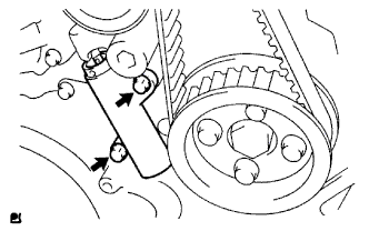
Alternately loosen the 2 bolts, and remove the timing belt tensioner.
-
Remove the timing belt.
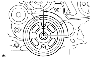
Tech Tips
-
When turning the camshaft with the timing belt removed first, turn the crankshaft 90° counterclockwise to lower the piston.
-
When installing the timing belt, first return the camshaft to the timing marks and then turn the crankshaft clockwise until it aligns with the timing marks.
-
-
-
REMOVE NO. 1 TIMING BELT IDLER SUB-ASSEMBLY
-
Using a 10 mm hexagon wrench, remove the bolt, timing belt idler and washer.
-
-
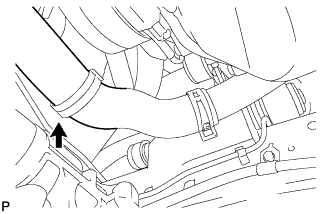
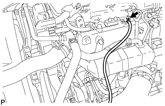
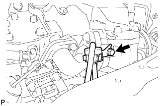
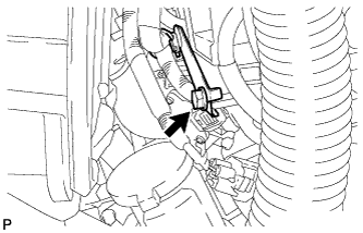
REMOVE NO. 1 AIR HOSE
-
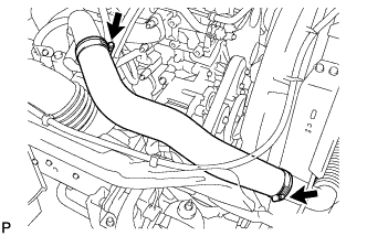
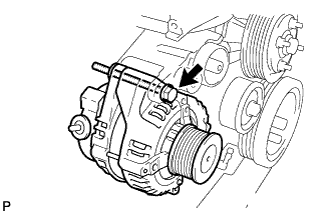
Loosen the hose clamp shown in the illustration and remove the No. 1 air hose.
-
-
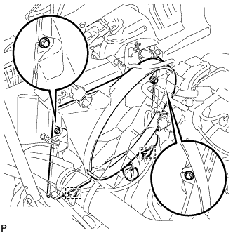
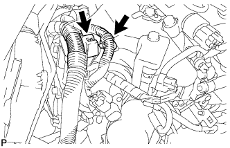
REMOVE GENERATOR
-
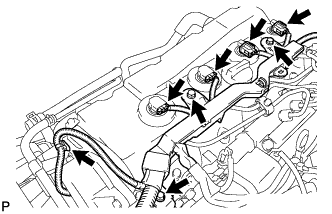
Remove the 2 bolts, disconnect the connector shown in the illustration and separate the engine wire harness (for LHD).
-
Remove the oil level gage sub-assembly (for LHD).
-
Remove the bolt and remove the oil level gage guide (for LHD).
-
Remove the 2 bolts, disconnect the connector shown in the illustration and separate the engine wire harness (for RHD).
-
Disconnect the generator connector.
-
Remove the terminal cap.
-
Remove the nut and disconnect the wire harness from terminal B.
-
Remove the 2 bolts and remove the generator bracket.
-
Remove the bolt and remove the generator.
-
-
REMOVE V-RIBBED BELT TENSIONER ASSEMBLY
-
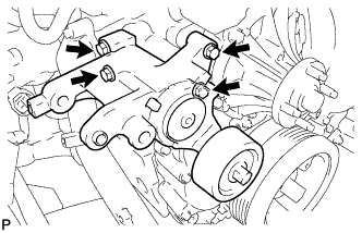
Remove the 4 bolts and belt tensioner.
-
-
REMOVE INJECTION PIPE SUB-ASSEMBLY
-
Separate the fuel injector connector and harness clamp.
-
Remove the 3 bolts and separate the wire harness.
-
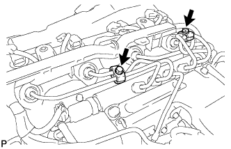
Remove the 2 bolts and remove the 2 No. 2 injection pipe clamps.
-
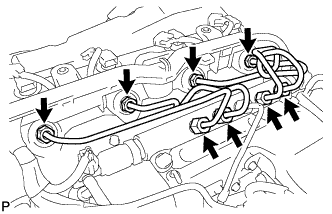
Using union nut wrench 17 mm, loosen the union nuts and remove the 4 injection pipe sub-assemblies.
-
-
REMOVE CYLINDER HEAD COVER SUB-ASSEMBLY
-
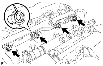
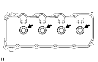
Insert a screwdriver into the cutout of the cylinder head cover sub-assembly and remove the 4 nozzle holder seals.
-
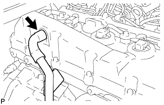
Disconnect the ventilation hose.
-
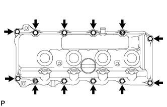
Remove the 10 bolts, 2 nuts, cylinder head cover sub-assembly and the cylinder head cover gasket.
-
Remove the 4 No. 3 cylinder head cover gaskets from the cylinder head cover sub-assembly.
-
-
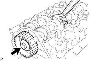
REMOVE CAMSHAFT TIMING PULLEY
-
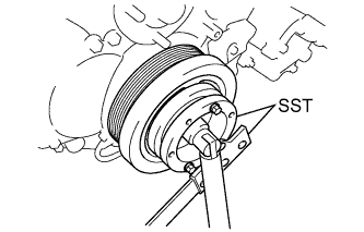
Remove the bolt from the camshaft timing pulley while holding the camshaft with a wrench.
-
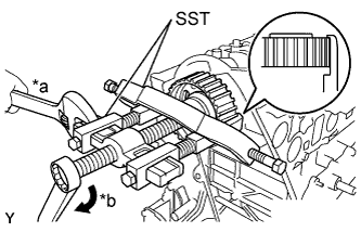
Text in Illustration *a Hold *b Turn Using SST, remove the camshaft timing pulley and set key.
- SST
- 09950-40011 ( 09951-04010, 09952-04010, 09953-04020, 09954-04010, 09955-04071, 09957-04010, 09958-04011 )
-
Rotate the crankshaft approximately 90° counterclockwise from the TDC position to lower the piston.
-
-
REMOVE NO. 2 TIMING BELT COVER
-
Remove the nut, 4 bolts and timing belt No. 2 cover.
-
-
REMOVE WATER PUMP
-
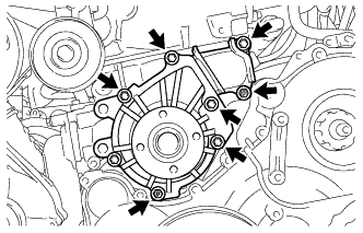
Remove the 2 nuts, 5 bolts, engine water pump assembly and the gasket from the cylinder block sub-assembly.
-
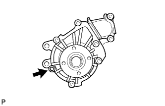
Remove the bolt, water pump assembly without cover and the gasket from the water pump cover.
-
-
REMOVE NO. 3 AIR HOSE
-
Slide the clip and disconnect the vacuum hose.
-
Loosen the 2 hose clamps and remove the No. 3 air hose.
-
-
SEPARATE VANE PUMP OIL RESERVOIR ASSEMBLY
-
Remove the 3 bolts and separate the vane pump oil reservoir.
Tech Tips
Remove the vane pump oil reservoir together with the 2 hoses, then suspended them from the body with piece of rope.
-
-
REMOVE VANE PUMP
-
Remove the 2 nuts, and then remove the vane pump and O-ring.
Tech Tips
Remove the vane pump together with hoses.
-
-
REMOVE TIMING GEAR COVER INSULATOR
-
Remove the bolt and timing gear cover insulator.
-
-
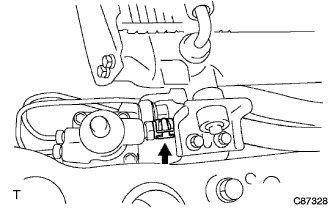
REMOVE VACUUM PUMP
-
Slide the clip and disconnect the 2 vacuum hoses from the vacuum pump union.
-
Remove the 2 nuts and remove the vacuum pump.
-
Remove the 2 O-rings from the vacuum pump.
-
-
REMOVE NO.4 AIR INJECTION SYSTEM HOSE (w/ Heater)
-
Loosen the 2 clamps and remove the No. 4 air injection system hose.
-
-
REMOVE DIESEL THROTTLE BODY ASSEMBLY (w/ Heater)
-
Disconnect the turbo pressure sensor connector and No. 1 vacuum switching valve assembly connector.
-
Remove the bolt and detach the wire harness clamp.
-
Disconnect the intake air temperature sensor connector.
-
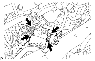
Disconnect the 2 diesel throttle body assembly connectors.
-
Remove the 2 bolts, 2 nuts, diesel throttle body assembly and gasket.
-
-
REMOVE NO.1 GAS FILTER (w/ Heater)
-
Remove the bolt and gas filter.
-
-
REMOVE ENGINE ROOM MAIN WIRE (w/ Heater)
-
Disconnect the EGR control valve connector.
-
Detach the 2 wire harness clamps.
-
Remove the bolt and detach the wire harness clamp.
-
Disconnect the connector.
-
Disconnect the vacuum hose.
-
-
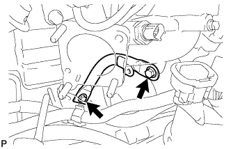
REMOVE MANIFOLD STAY (w/ Heater)
-
Detach the wire harness.
-
Remove the 2 bolts and manifold stay.
-
-
REMOVE ELECTRIC EGR CONTROL VALVE ASSEMBLY (w/ Heater)
-
Disconnect the vacuum regulating valve connector.
-
Disconnect the 2 vacuum hoses from the vacuum regulating valve.
-
Remove the 2 bolts and remove the vacuum regulating valve with bracket.
-
Remove the 2 bolts and detach the No. 2 EGR pipe.
-
Remove the bolt, 2 nuts, electric EGR control valve with intake air connector and 3 gaskets from the intake manifold.
-
Disconnect the vacuum hose.
-
-
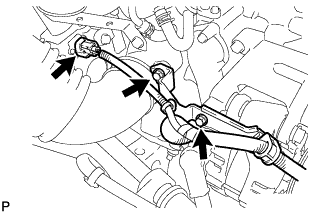
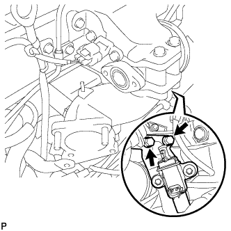
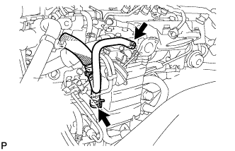
DISCONNECT NO.4 VACUUM TRANSMITTING HOSE ASSEMBLY (w/ Heater)
-
Disconnect the No. 4 vacuum transmitting hoses from the EGR cooler assembly as shown in the illustration.
-
-
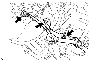
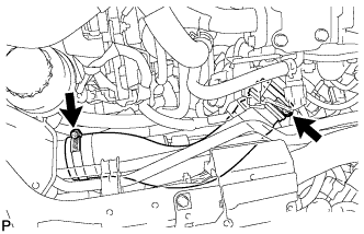
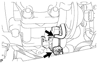
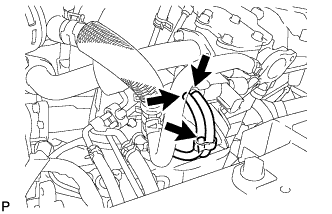
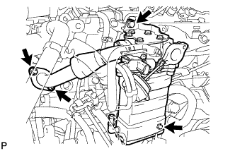
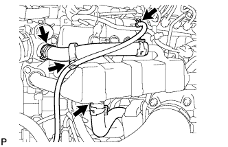
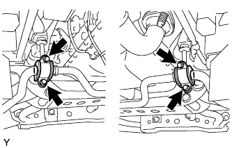
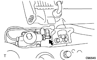
DISCONNECT WATER BY-PASS HOSE (w/ Heater)
-
Loosen the 2 clamps and disconnect the 2 water by-pass hoses as shown in the illustration.
-
-
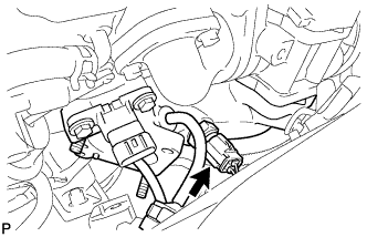
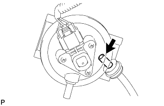
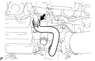
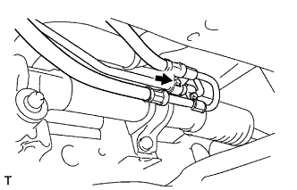
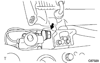
DISCONNECT NO.3 WATER BY-PASS HOSE (w/ Heater)
-
Loosen the clamp and disconnect the No. 3 water by-pass hose as shown in the illustration.
-
-
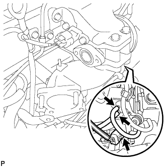
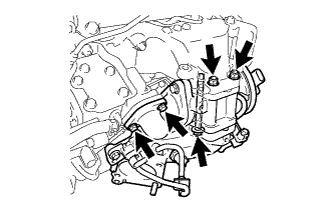
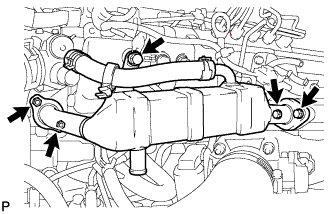
REMOVE EGR COOLER ASSEMBLY (w/ Heater)
-
Remove the 2 bolts, 2 nuts, EGR cooler assembly and gasket.
-
-
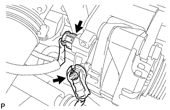
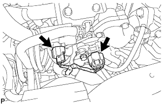
REMOVE DIESEL THROTTLE BODY (w/o Heater)
-
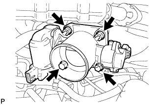
Disconnect the 2 connectors.
-
Remove the 2 nuts and 2 bolts and remove the diesel throttle body and gasket.
-
-
REMOVE EGR COOLER ASSEMBLY (w/o Heater)
-
Loosen the clamp and disconnect the oil return hose.
-
Loosen the clamp and disconnect the No. 4 water by-pass hose.
-
Loosen the clamp and disconnect the No. 2 water by-pass hose.
-
Remove the 3 bolts, 2 nuts, EGR cooler assembly and 2 gaskets.
-
-
REMOVE OIL LEVEL GAGE GUIDE (w/o Heater)
-
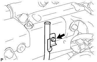
Remove the oil level gage sub-assembly.
-
Remove the bolt and remove the oil level gage guide.
-
-
REMOVE FUEL INLET PIPE SUB-ASSEMBLY
-
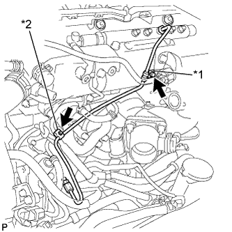
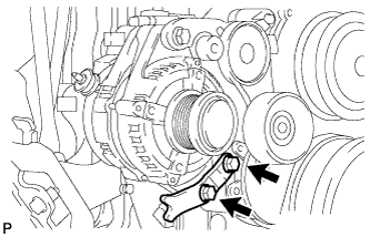
Text in Illustration *1 No. 1 Clamp *2 No. 2 Clamp Remove the bolt and remove the No. 1 injection pipe clamp.
-
Remove the bolt and remove the No. 2 injection pipe clamp.
-
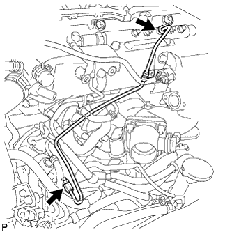
Using union nut wrench 17 mm, loosen the union nuts and remove the fuel inlet pipe sub-assembly.
-
-
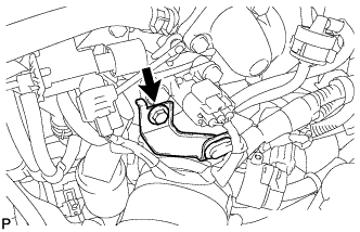
REMOVE MANIFOLD STAY
-
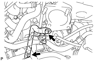
Remove the wire harness and 2 bolts and remove the manifold stay.
-
-
REMOVE PUMP DRIVE SHAFT PULLEY
-
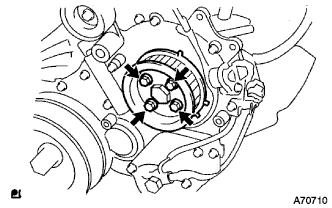
Remove the 4 bolts and remove camshaft timing pulley flange No. 2 and pump drive shaft pulley.
-
-
REMOVE FUEL SUPPLY PUMP
-
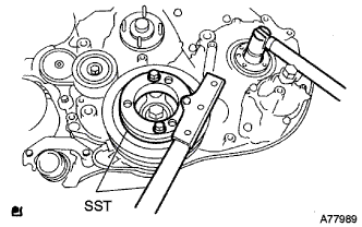
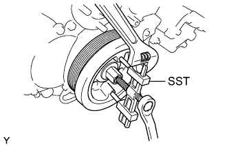
Using SST, secure the crankshaft pulley and remove the supply pump gear set nut and O-ring.
- SST
- 09213-58013
- 09330-00021
-
Disconnect the 2 connectors from the fuel supply pump.
-
Disconnect the 3 fuel hoses from the fuel supply pump.
-
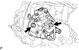
Loosen the 2 nuts.
Note
Do not remove the nuts.
-
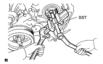
Using SST, disengage the fuel supply pump from the supply pump gear.
- SST
- 09950-50013 ( 09951-05010, 09952-05010, 09953-05020, 09954-05021 )
-
Remove the 2 nuts and remove the fuel supply pump.
-
Remove the O-ring and pulley key from the fuel supply pump.
-
-
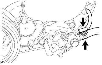
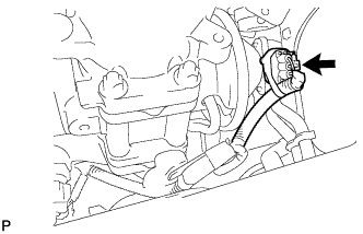
REMOVE CRANKSHAFT POSITION SENSOR
-
Disconnect the crankshaft position sensor connector.
-
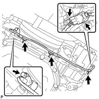
Detach the 3 wire harness clamps.
-
Remove the bolt and remove the crankshaft position sensor.
-
-
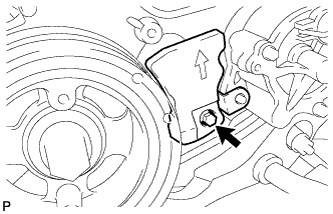
REMOVE CAMSHAFT POSITION SENSOR
-
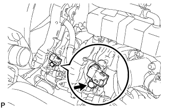
Disconnect the camshaft position sensor connector.
-
Remove the bolt and remove the camshaft position sensor.
-
-
REMOVE CRANKSHAFT PULLEY
-
Using SST, hold the crankshaft pulley and loosen the bolt.
- SST
- 09213-58013
- 09330-00021
-
Using SST, remove the crankshaft pulley.
- SST
- 09950-50013 ( 09951-05010, 09952-05010, 09953-05010, 09954-05021 )
-
-
SEPARATE TIE ROD END SUB-ASSEMBLY LH
-
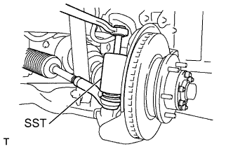
Remove the cotter pin and nut.
-
Using SST, disconnect the tie rod end from the steering knuckle arm.
- SST
- 09610-20012
-
-
SEPARATE TIE ROD END SUB-ASSEMBLY RH
Tech Tips
The removal procedure for the RH side is the same as that for the LH side.
-
SEPARATE FRONT SHOCK ABSORBER ASSEMBLY LH
-
Remove the bolt and nut, disconnect the front shock absorber LH from the suspension lower arm.
-
-
SEPARATE FRONT SHOCK ABSORBER ASSEMBLY RH
Tech Tips
The removal procedure for the RH side is the same as that for the LH side.
-
SEPARATE FRONT STABILIZER BAR
-
Remove the 4 bolts and separate the front stabilizer bar.
-
-
SEPARATE FRONT LOWER BALL JOINT ASSEMBLY LH
-
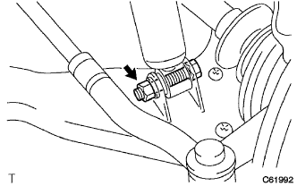
Remove the cotter pin and castle nut.
-

Text in Illustration *a Hold *b Turn Using SST, disconnect the lower ball joint from suspension lower arm.
- SST
- 09628-62011
-
-
SEPARATE FRONT LOWER BALL JOINT ASSEMBLY RH
Tech Tips
The removal procedure for the RH side is the same as that for the LH side.
-
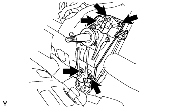
REMOVE STEERING TORQUE SHAFT ASSEMBLY
-
Remove the 3 bolts, steering link protector UPR and steering link protector LWR.
-
Remove the 2 bolts.
-
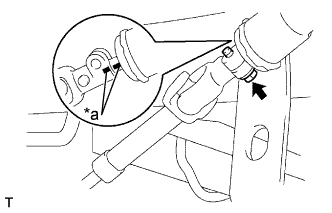
Text in Illustration *a Matchmark Shift the sliding yoke and place the matchmarks to the sliding yoke and steering gear.
-
Remove the bolt.
-
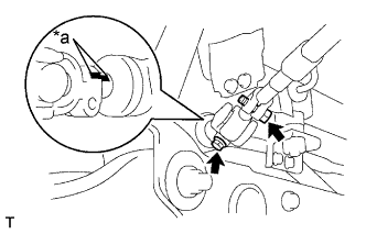
Text in Illustration *a Matchmark Shift the torque shaft and place the matchmarks to the torque shaft and bevel gear.
-
Remove the torque shaft.
-
-
SEPARATE STEERING GEAR OUTLET RETURN TUBE
-
Remove the bolt (LHD steering position type only).
-
Remove the clip and disconnect the return hose.
-
Remove the return tube.
-
-
SEPARATE PRESSURE FEED TUBE ASSEMBLY
-
Remove the union bolt and gasket, and disconnect the feed tube.
-
-
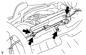
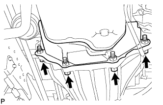
REMOVE FRONT SUSPENSION MEMBER ASSEMBLY
-
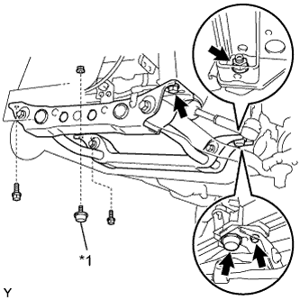
Text in Illustration *1 Front Suspension Damper Set a jack under the front suspension member.
-
Remove the 2 nuts and the 2 suspension dampers.
-
Remove the 4 bolts, and then remove the front suspension member.
-
-
REMOVE NO. 2 REAR END PLATE
-
Remove the 4 bolts.
-
Remove the No. 4 cylinder block insulator and No. 2 rear end plate.
-
-
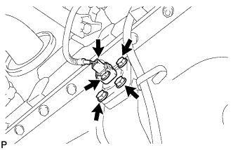
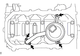
REMOVE ENGINE OIL LEVEL SENSOR
-
Disconnect the engine oil level sensor connector.
-
Remove the 4 bolts and engine oil level sensor from the oil pan.
-
Remove the gasket from the engine oil level sensor.
-
-
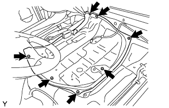
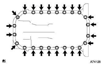
REMOVE OIL PAN SUB-ASSEMBLY
-
Remove the vinyl tube from the oil pan.
-
Remove the 22 bolts and 2 nuts.
-
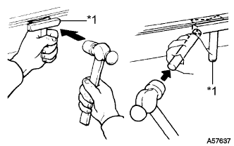
Text in Illustration *1 Oil Pan Seal Cutter Insert the blade of Oil Pan Seal cutter between the oil pan and cylinder block, cut through the applied sealer and remove the oil pan.
Note
-
Do not use Oil Pan Seal cutter for the timing belt case side and rear oil seal retainer.
-
Be careful not to damage the oil pan flange.
-
-
w/ Heater:
Remove the stiffening plate.
-
-
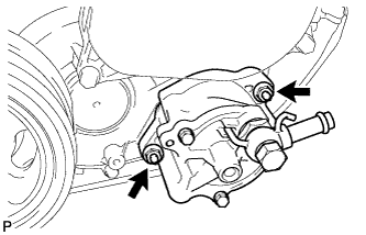
REMOVE OIL STRAINER SUB-ASSEMBLY
-
Remove the 2 nuts and 2 bolts and remove the oil strainer and gasket.
-
-
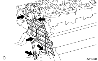
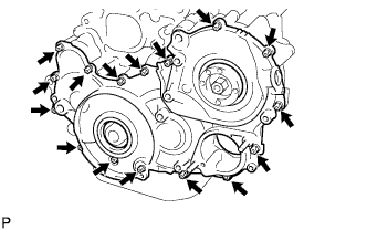
REMOVE TIMING GEAR CASE
-
Remove the 14 bolts and 2 nuts.
-
Pry the timing gear case at the locations shown in the illustration and remove the timing gear case.
Note
Do not damage the contact surface.
-
Remove the O-ring.
-
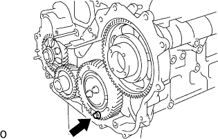
Secure the idle sub gears to the No. 1 idle gear with a service bolt.
-
-
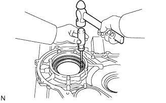
REMOVE TIMING CHAIN OR BELT COVER OIL SEAL
-
Using a screwdriver and hammer, tap out the oil seal.
-
-
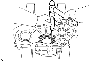
REMOVE TIMING GEAR CASE OR TIMING CHAIN CASE OIL SEAL
-
Using a screwdriver and hammer, tap out the oil seal.
-
-
REMOVE NO. 1 CRANKSHAFT POSITION SENSOR PLATE
-
Remove the No. 1 crankshaft position sensor plate.
-
-
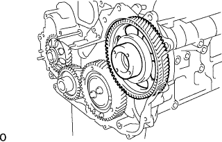
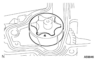
REMOVE INJECTION GEAR
-
Remove the injection gear.
-
-
REMOVE CRANKSHAFT TIMING GEAR
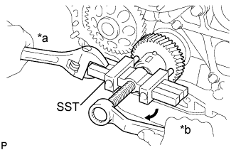
Text in Illustration *a Hold *b Turn
-
Using SST, remove the crankshaft timing gear.
- SST
- 09950-50013 ( 09951-05010, 09952-05010, 09953-05010, 09954-05011 )
-
-
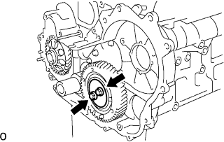
REMOVE IDLE GEAR THRUST PLATE
-
Remove the 2 bolts and idle gear thrust plate.
-
-
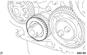
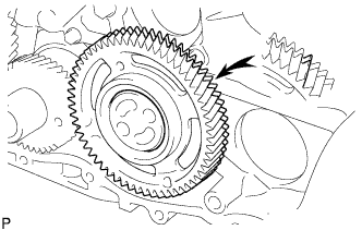
REMOVE IDLE GEAR
-
Remove the idle gear from the No. 1 idle gear shaft.
Note
Make sure that the idle sub gear and No. 1 idle gear are correctly fitted to each other.
-
-
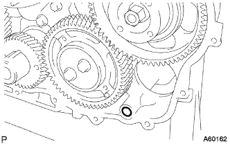
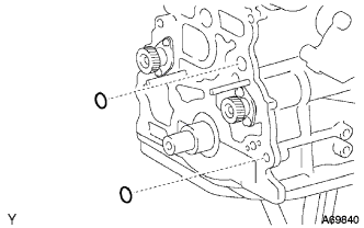
REMOVE NO. 1 IDLE GEAR SHAFT
-
Remove the No. 1 idle gear shaft.
-
-
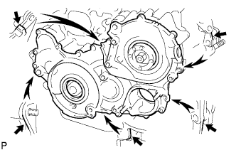
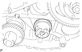
REMOVE TIMING GEAR CASE ASSEMBLY
-
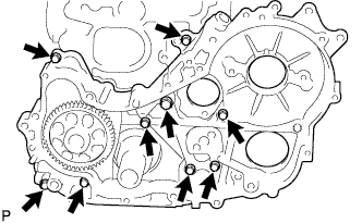
Remove the union bolt and 8 bolts.
-
Text in Illustration *1 Protective Tape Pry the timing gear case at the locations shown in the illustration and remove the timing gear case.
Note
Do not drop the driven rotor.
-
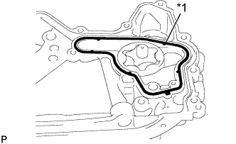
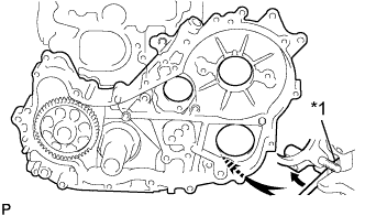
Text in Illustration *1 Gasket Remove the gasket from the timing gear case.
-
Remove the driven rotor from the timing gear case.
-
Remove the 2 O-rings from the cylinder block.
-