OIL PUMP (w/ DPF) REMOVAL

Note
-
When replacing the injectors (including shuffling the injectors between the cylinders), common rail or cylinder head, it is necessary to replace the injection pipes with new ones.
-
When replacing the fuel supply pump, common rail, cylinder block, cylinder head, cylinder head gasket or timing gear case, it is necessary to replace the fuel inlet pipe with a new one.
-
After removing the injection pipes, clean them with a brush and compressed air.
-
PRECAUTION
After turning the ignition switch off, waiting time may be required before disconnecting the cable from the battery terminal. Therefore, make sure to read the disconnecting the cable from the battery terminal notice before proceeding with work Click here.
-
DISCONNECT CABLE FROM NEGATIVE BATTERY TERMINAL
-
REMOVE FRONT WHEEL
-
DRAIN ENGINE COOLANT
CAUTION:
To avoid the danger of being burned, do not remove the radiator cap while the engine and radiator are still hot. Thermal expansion will cause hot engine coolant and steam to blow out from the radiator.
-
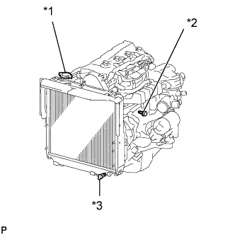
Text in Illustration *1 Radiator Cap *2 Engine Drain Plug *3 Radiator Drain Plug Loosen the radiator drain plug (on the radiator).
-
Remove the radiator cap.
-
Loosen the engine drain plug (on the oil cooler cover), and drain the coolant.
-
Drain the coolant from the reservoir tank.
-
Tighten the engine drain plug.
- Torque:
- 8.0 N*m { 82 kgf*cm, 71 in.*lbf }
-
-
DRAIN ENGINE OIL
-
Remove the oil filler cap.
-
Remove the drain plug from the oil pan and drain the engine oil into a container.
-
Clean the drain plug.
-
Install the drain plug with a new gasket.
- Torque:
- 34 N*m { 347 kgf*cm, 25 ft.*lbf }
-
-
REMOVE ENGINE SERVICE HOLE SUB COVER SUB-ASSEMBLY (for Double Cab)
-
REMOVE ENGINE WATER PUMP
-
REMOVE SUPPLY PUMP ASSEMBLY
-
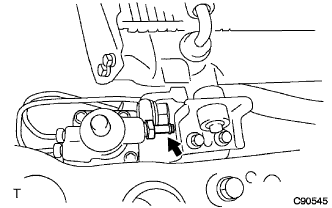
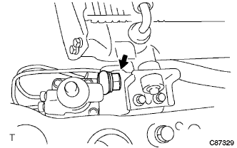
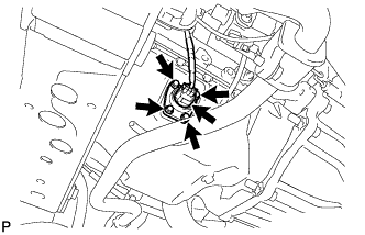
REMOVE VACUUM PUMP
-
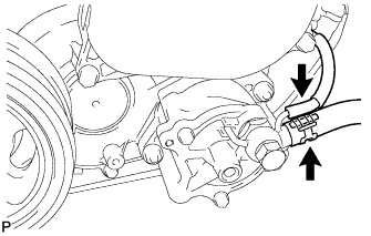
Slide the clip and disconnect the 2 vacuum hoses from the vacuum pump union.
-
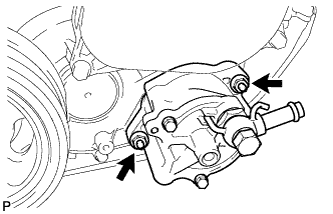
Remove the 2 nuts and remove the vacuum pump.
-
Remove the 2 O-rings from the vacuum pump.
-
-
REMOVE CRANKSHAFT POSITION SENSOR
-
TYPE A:
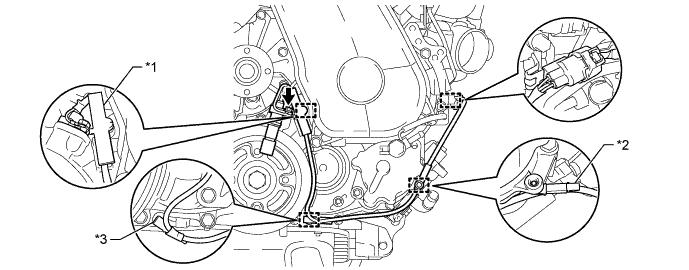
Text in Illustration *1 Clamp *2 Wire Harness Clamps (A) *3 Wire Harness Clamps (B) - -
-
Detach the 2 wire harness clamps (A, B).
-
Disconnect the crankshaft position sensor connector.
-
Detach the crankshaft position sensor connector from the No. 1 vacuum transmitting pipe.
-
Remove the clamp.
Note
-
Make sure that no portion of the clamp remains in the clamp installation hole. If there is any portion of the clamp remaining, remove it.
-
Do not reuse the clamp.
-
-
Remove the bolt and crankshaft position sensor.
-
-
TYPE B:
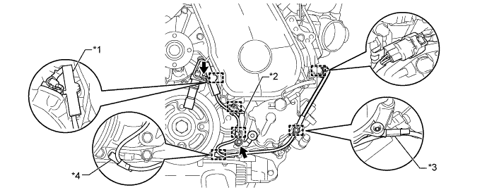
Text in Illustration *1 Clamp *2 Bracket (Clamp) *3 Wire Harness Clamps (A) *4 Wire Harness Clamps (B)
-
Detach the 2 wire harness clamps (A, B).
-
Disconnect the crankshaft position sensor connector.
-
Detach the crankshaft position sensor connector from the No. 1 vacuum transmitting pipe.
-
Remove the clamp.
Note
-
Make sure that no portion of the clamp remains in the clamp installation hole. If there is any portion of the clamp remaining, remove it.
-
Do not reuse the clamp.
-
-
Remove the bolt and bracket (clamp).
-
Remove the bolt and crankshaft position sensor.
-
Detach the 2 wire harness clamps from the bracket (clamp).
-
-
-
REMOVE CAMSHAFT POSITION SENSOR
-
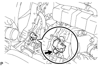
Disconnect the camshaft position sensor connector.
-
Remove the bolt and remove the camshaft position sensor.
-
-
REMOVE OIL PRESSURE SWITCHING VALVE ASSEMBLY
-
Disconnect the oil pressure switching valve connector.
-
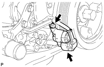
Remove the bolt and oil pressure switching valve.
-
-
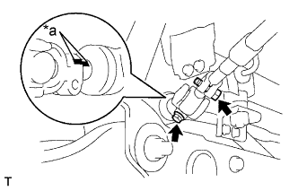
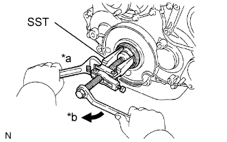
REMOVE CRANKSHAFT PULLEY
-
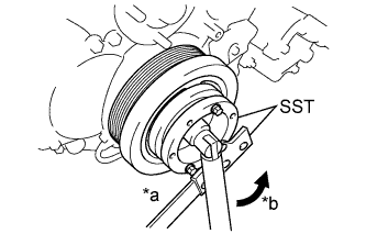
Text in Illustration *a Hold *b Turn Using SST, loosen the pulley bolt.
- SST
- 09213-58014
- 09330-00021
-
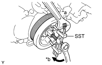
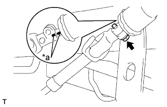
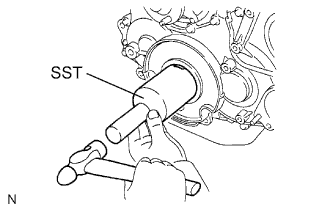
Text in Illustration *a Hold *b Turn Using SST, remove the pulley bolt and pulley.
- SST
- 09950-50013 ( 09951-05010, 09952-05010, 09953-05020, 09954-05021 )
Note
Apply oil or grease to the threads and tip of SST (center bolt) before to using it.
-
-
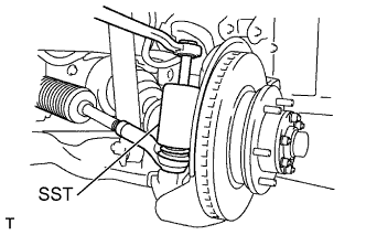
SEPARATE TIE ROD END SUB-ASSEMBLY LH
-
Remove the cotter pin and nut.
-
Using SST, disconnect the tie rod end from the steering knuckle arm.
- SST
- 09610-20012
-
-
SEPARATE TIE ROD END SUB-ASSEMBLY RH
Tech Tips
The removal procedure for the RH side is the same as that for the LH side.
-
SEPARATE FRONT SHOCK ABSORBER ASSEMBLY LH
-
Remove the bolt and nut, disconnect the front shock absorber LH from the suspension lower arm.
-
-
SEPARATE FRONT SHOCK ABSORBER ASSEMBLY RH
Tech Tips
The removal procedure for the RH side is the same as that for the LH side.
-
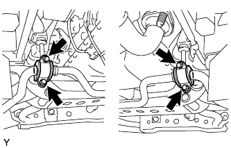
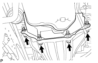
SEPARATE FRONT STABILIZER BAR
-
Remove the 4 bolts and separate the front stabilizer bar.
-
-
SEPARATE FRONT LOWER BALL JOINT ASSEMBLY LH
-
Remove the cotter pin and castle nut.
-

Text in Illustration *a Hold *b Turn Using SST, disconnect the lower ball joint from suspension lower arm.
- SST
- 09628-62011
-
-
SEPARATE FRONT LOWER BALL JOINT ASSEMBLY RH
Tech Tips
The removal procedure for the RH side is the same as that for the LH side.
-
REMOVE STEERING TORQUE SHAFT ASSEMBLY
-
Remove the 3 bolts, steering link protector UPR and steering link protector LWR.
-
Remove the 2 bolts.
-
Text in Illustration *a Matchmark Shift the sliding yoke and place the matchmarks to the sliding yoke and steering gear.
-
Remove the bolt.
-
Text in Illustration *a Matchmark Shift the torque shaft and place the matchmarks to the torque shaft and bevel gear.
-
Remove the torque shaft.
-
-
SEPARATE STEERING GEAR OUTLET RETURN TUBE
-
Remove the bolt (LHD steering position type only).
-
Remove the clip and disconnect the return hose.
-
Remove the return tube.
-
-
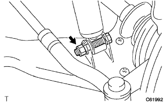
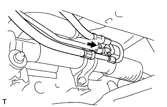
SEPARATE PRESSURE FEED TUBE ASSEMBLY
-
Remove the union bolt and gasket, and disconnect the feed tube.
-
-
REMOVE FRONT SUSPENSION MEMBER ASSEMBLY
-
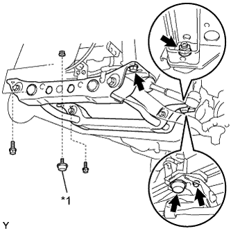
Text in Illustration *1 Front Suspension Damper Set a jack under the front suspension member.
-
Remove the 2 nuts and the 2 suspension dampers.
-
Remove the 4 bolts and front suspension member.
-
-
REMOVE NO. 2 REAR END PLATE
-
Remove the 4 bolts.
-
Remove the No. 4 cylinder block insulator and No. 2 rear end plate.
-
-
REMOVE ENGINE OIL LEVEL SENSOR
-
Disconnect the engine oil level sensor connector.
-
Remove the 4 bolts and engine oil level sensor.
-
Remove the gasket from the engine oil level sensor.
-
-
REMOVE OIL PAN SUB-ASSEMBLY
-
Disconnect the vinyl tube from the oil pan.
-
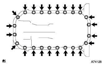
Remove the 22 bolts and 2 nuts.
-
Insert the blade of an oil pan seal cutter between the oil pan and cylinder block, cut through the applied sealer and remove the oil pan.
Note
-
Do not use Oil Pan Seal cutter for the timing belt case side and rear oil seal retainer.
-
Be careful not to damage the oil pan flange.
-
-
-
REMOVE OIL STRAINER SUB-ASSEMBLY
-
Remove the 2 bolts, 2 nuts, oil strainer and gasket.
-
-
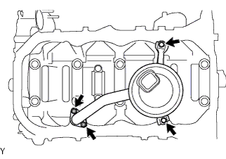
REMOVE NO. 1 VACUUM TRANSMITTING PIPE SUB-ASSEMBLY
-
Disconnect the vacuum hose.
-
Remove the nut, bolt and No. 1 vacuum transmitting pipe.
-
-
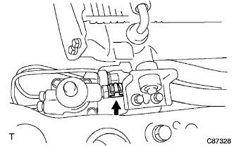
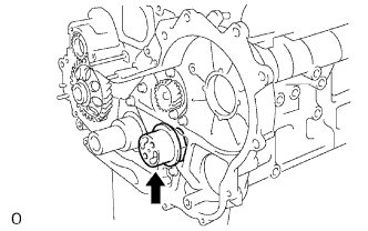
REMOVE OIL CHECK VALVE SUB-ASSEMBLY
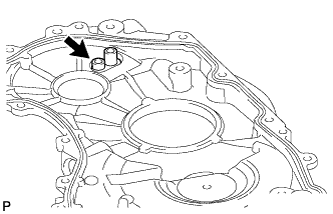
-
Using a 6 mm hexagon wrench, remove the bolt and oil check valve from the timing gear case.
-
-
INSPECT OIL CHECK VALVE SUB-ASSEMBLY
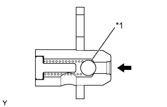
Text in Illustration *1 Ball
-
Push the ball of the oil check valve to check if it is stuck.
If the check valve is stuck, replace the oil check valve.
-
-
REMOVE TIMING GEAR CASE
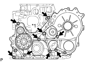
-
Remove the union bolt and 8 bolts.
Text in Illustration *1 Union Bolt -
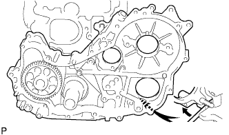
Pry the gear case in the location shown in the illustration, and remove the gear case.
Note
Be careful not to drop the oil pump rotor.
-
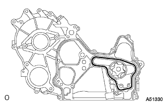
Remove the rotor and gasket.
-
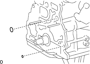
Remove the 2 O-rings.
-
-
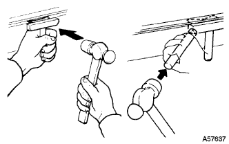
REMOVE TIMING GEAR CASE OIL SEAL
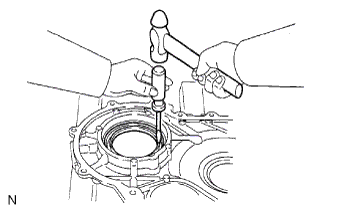
Tech Tips
There are 2 methods to remove the oil seal.
-
If the timing gear cover is removed from the cylinder block:
-
Using a screwdriver and hammer, tap out the oil seal.
-
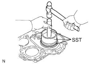
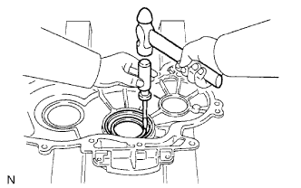
Using SST and a hammer, tap in a new oil seal until its surface is flush with the timing gear cover edge.
- SST
- 09223-15020
- 09502-12010
- 09950-70010 ( 09951-07100 )
-
Apply MP grease to the oil seal lip.
-
-
If the timing gear cover is installed to the cylinder block:
-
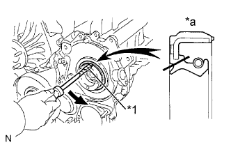
Text in Illustration *1 Protective Tape *a Cut Position Using a knife, cut through the oil seal lip.
-
Using a screwdriver, pry out the oil seal.
Note
Be careful not to damage the crankshaft.
-
Apply MP grease to the oil seal lip.
-
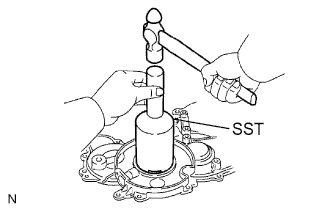
Using SST and a hammer, tap in a new oil seal until its surface is flush with the timing gear cover edge.
- SST
- 09223-15020
- 09502-12010
- 09950-70010 ( 09951-07100 )
-
-
-
REMOVE TIMING GEAR COVER OIL SEAL
Tech Tips
There are 2 methods to remove the oil seal.
-
If the timing gear cover is removed from the cylinder block.
-
Using a screwdriver and a hammer, tap out the oil seal.
-
Using SST and a hammer, tap in a new oil seal until its surface is flush with the timing gear cover edge.
- SST
- 09214-76011
-
Apply MP grease to a new oil seal lip.
-
-
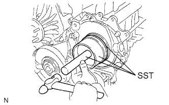
If the timing gear cover is installed to the cylinder block.
-
Using SST, remove the oil seal.
Text in Illustration *a Hold *b Turn - SST
- 09308-10010
- 09950-40011 ( 09957-04010 )
- 09950-60010 ( 09951-00350 )
-
Apply MP grease to a new oil seal lip.
-
Using SST and a hammer, tap in the oil seal until its surface is flush with the timing gear cover edge.
- SST
- 09214-76011
-
-
-
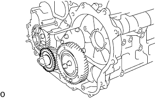
REMOVE INJECTION GEAR
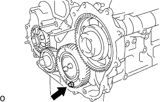
-
Secure the idle sub-gear to the idle gear with a service bolt.
- Torque:
- 8.0 N*m { 82 kgf*cm, 71 ft.*lbf }
Note
If the bolt hole of the No. 2 idle sub gear is not aligned with the bolt hole of the No. 1 idle gear, rotate the crankshaft counterclockwise to align the bolt holes. Then install the service bolt.
-
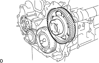
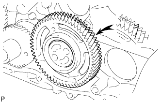
Remove the injection gear.
-
-
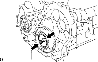
REMOVE NO. 1 CRANKSHAFT POSITION SENSOR PLATE
-
Remove the No. 1 crankshaft position sensor plate.
-
-
REMOVE CRANKSHAFT TIMING GEAR
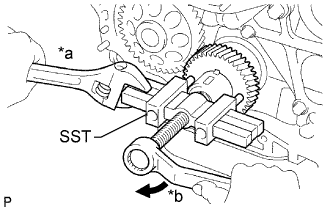
Text in Illustration *a Hold *b Turn
-
Using SST, remove the crankshaft timing gear.
- SST
- 09950-50013 ( 09951-05010, 09952-05010, 09953-05010, 09954-05021 )
-
-
REMOVE IDLE GEAR THRUST PLATE
-
Remove the 2 bolts and idle gear thrust plate.
-
-
REMOVE NO. 1 IDLE GEAR ASSEMBLY
-
Remove the idle gear from the No. 1 idle gear shaft.
Note
Make sure that the idle sub gear and No. 1 idle gear are correctly fitted to each other.
-
-
REMOVE NO. 1 IDLE GEAR SHAFT
-
Remove the idle gear shaft.
-
-
REMOVE TIMING GEAR CASE ASSEMBLY
-
Remove the union bolt and 8 bolts.
Text in Illustration *1 Union Bolt -
Pry the gear case in the location shown in the illustration, and remove the gear case.
Note
Be careful not to drop the oil pump rotor.
-
Remove the rotor and gasket.
-
Remove the 2 O-rings.
-
-
REMOVE STRAIGHT SCREW PLUG
-
Remove the screw plug and gasket.
-