OIL PUMP INSTALLATION

-
INSTALL TIMING GEAR CASE SUB-ASSEMBLY
-
Place anew gasket on the cylinder block.
-
Install the timing belt case with the 5 bolts.
- Torque:
- 29.5 N*m { 300 kgf*cm, 22 ft.*lbf }
-
-
INSTALL OIL STRAINER SUB-ASSEMBLY
-
Install a new gasket and the oil strainer with the 2 bolts and 2 nuts.
- Torque:
- for Nut
- 21 N*m { 210 kgf*cm, 15 ft.*lbf }
- for Bolt
- 18 N*m { 180 kgf*cm, 13 ft.*lbf }
-
-
INSTALL OIL PAN SUB-ASSEMBLY
-
Remove any old packing (FIPG) material and be careful not to drop any oil on the contact surfaces of the oil pan and cylinder block.
-
Using a razor blade and gasket scraper, remove all the old packing (FIPG) material from the gasket surfaces and sealing groove.
-
Thoroughly clean all components to remove all the loose material.
-
Using a non-residue solvent, clean both sealing surfaces.
Note
Do not use a solvent which affects the painted surfaces.
-
-
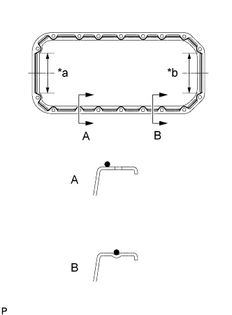
Text in Illustration *a 128 mm (5.04 in.) Timing Belt Case Contact Portion *b 128 mm (5.04 in.) Rear Oil Seal Contact Portion Apply seal packing to the oil pan as shown in the illustration.
Tech Tips
Apply at least 5 mm (0.20 in.) (preferably slightly more) of seal packing to the portions of the oil pan in contact with the timing belt case and rear oil seal retainer.
Seal packing Toyota Genuine Seal Packing Black, Three Bond 1207B or equivalent
-
Install a nozzle that has been cut to a 4 - 5mm(0.16 - 0.20 in.) opening.
Tech Tips
Avoid applying an excessive amount to the surface. Be particularly careful near oil passages.
-
Parts must be assembled within 5 minutes of application. Otherwise, the material must be removed and reapplied.
-
Immediately remove the nozzle from the tube and reinstall, cap.
-
-
Install be oil pan with the 14 bolts and 4 nuts. Uniformly tighten the bolts and nuts in several passes.
- Torque:
- 18 N*m { 180 kgf*cm, 13 ft.*lbf }
-
-
INSTALL FRONT SUSPENSION MEMBER ASSEMBLY (INDEPENDENT FRONT SUSPENSION)
-
Using an engine lifter, install the front suspension member assembly with the 4 bolts.
- Torque:
- 150 N*m { 1530 kgf*cm, 110 ft.*lbf }
-
Install the front stabilizer cover RH and LH.
- Torque:
- 18 N*m { 185 kgf*cm, 13 ft.*lbf }
-
Install the front shock absorber assembly RH and LH at the lower arm part.
- Torque:
- 105 N*m { 1070 kgf*cm, 77 ft.*lbf }
-
-
INSTALL PRESSURE FEED TUBE ASSEMBLY (INDEPENDENT FRONT SUSPENSION)
-
Connect the tube with the union bolt and a new gasket.
- Torque:
- 42.1 N*m { 430 kgf*cm, 31 ft.*lbf }
-
-
INSTALL STEERING TORQUE SHAFT ASSEMBLY (INDEPENDENT FRONT SUSPENSION)
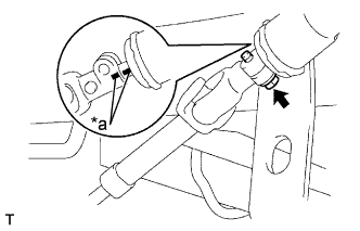
Text in Illustration *a Matchmark
-
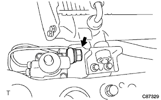
Align the matchmarks on the torque shaft and bevel gear.
-
Tighten the bolt.
- Torque:
- 35 N*m { 357 kgf*cm, 26 ft.*lbf }
-
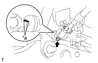
Text in Illustration *a Matchmark Align the matchmarks on the sliding yoke and steering gear.
-
Tighten the bolt.
- Torque:
- 35 N*m { 357 kgf*cm, 26 ft.*lbf }
-
-
INSTALL FRONT SPRING BUMPER NO.1 (INDEPENDENT FRONT SUSPENSION)
- Torque:
- 120 N*m { 1225 kgf*cm, 88 ft.*lbf }
-
INSTALL TIE ROD END SUB-ASSEMBLY LH (INDEPENDENT FRONT SUSPENSION)
-
Connect the tie rod end to the knuckle arm.
-
Install the nuts and new cotter pin.
- Torque:
- 91 N*m { 928 kgf*cm, 67 ft.*lbf }
-
-
INSTALL TIE ROD END SUB-ASSEMBLY RH (INDEPENDENT FRONT SUSPENSION)
Tech Tips
Connect the RH side by the same procedures with the LH side.
-
INSTALL TIE ROD END SUB-ASSEMBLY LH (RIGID FRONT SUSPENSION)
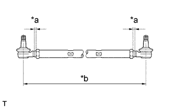
Text in Illustration *a 6.5 mm (0.3 in) *b 1163 mm (45.8 in)
-
Screw the lock nuts and tie rod ends into the tie rod.
Tech Tips
The tie rod length should be approximately 1163 mm (45.8 in.), and the remaining length of threads on both tie rods should be equal.
-
-
INSTALL TIE ROD END SUB-ASSEMBLY RH (RIGID FRONT SUSPENSION)
Tech Tips
Install the RH side by the same procedures with the LH side.
-
INSTALL CYLINDER BLOCK INSULATOR NO.5
-
INSTALL STIFFENER PLATE LH(MTM)
- Torque:
- M10
- 37.2 N*m { 380 kgf*cm, 27 ft.*lbf }
- M12
- 68.6 N*m { 700 kgf*cm, 51 ft.*lbf }
-
INSTALL STIFFENER PLATE LH (ATM)
- Torque:
- M10
- 37.2 N*m { 380 kgf*cm, 27 ft.*lbf }
- M12
- 68.6 N*m { 700 kgf*cm, 51 ft.*lbf }
-
INSTALL CYLINDER BLOCK INSULATOR NO.4
-
INSTALL STIFFENER PLATE RH(MTM)
- Torque:
- M10
- 37.2 N*m { 380 kgf*cm, 27 ft.*lbf }
- M12
- 68.6 N*m { 700 kgf*cm, 51 ft.*lbf }
-
INSTALL STIFFENER PLATE RH(ATM)
- Torque:
- M10
- 37.2 N*m { 380 kgf*cm, 27 ft.*lbf }
- M12
- 68.6 N*m { 700 kgf*cm, 51 ft.*lbf }
-
INSTALL TIMING BELT IDLER SUB-ASSEMBLY NO.2
-
Install the spacer and idler pulley with the bolt.
- Torque:
- 33 N*m { 340 kgf*cm, 24 ft.*lbf }
-
Check that the idler pulley moves smoothly.
-
-
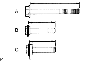
INSTALL TIMING BELT IDLER SUB-ASSEMBLY NO.1
Tech Tips
-
The bolt lengths for bolt types A, B and C shown in the illustration are:
A: 76.5 mm (3.012 in.)
B: 42.9 mm (1.689 in.), Color: Yellow
C: 41.3 mm (1.626 in.), Color: Silver
-
Bolt C is combined with the idler pulley.
-
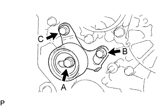
Install the idler pulley with the 3 bolts.
-
Tighten the bolt (C).
- Torque:
- 19 N*m { 195 kgf*cm, 14 ft.*lbf }
-
-
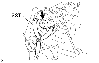
INSTALL CRANKSHAFT TIMING PULLEY
-
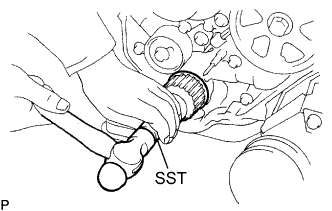
Using SST, install the timing pulley.
- SST
- 09223-50010
-
-
INSTALL WATER PUMP ASSEMBLY
-
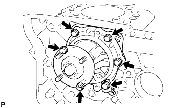
Install a new gasket, the water pump and tension spring bracket with the 6 bolts.
- Torque:
- 22.5 N*m { 230 kgf*cm, 17 ft.*lbf }
-
-
INSTALL TIMING BELT NO.2 COVER
- Torque:
- 18 N*m { 185 kgf*cm, 13 ft.*lbf }
-
INSTALL CAMSHAFT TIMING PULLEY
-
Install the set key to the key groove of the camshaft.
-
Align the pulley set key with the timing mark outward.
-
Using SST, install the pulley with the bolt.
- SST
- 09960-10010 ( 09962-01000, 09963-01000 )
- Torque:
- 98 N*m { 1000 kgf*cm, 72 ft.*lbf }
-
-
INSTALL HEATER WATER INLET HOSE A (W/ HEATER)
-
INSTALL ENGINE UNDER COVER SUB-ASSEMBLY NO.2
-
INSTALL ENGINE UNDER COVER SUB-ASSEMBLY NO.1
-
INSTALL INJECTION PUMP ASSEMBLY
-
ADD ENGINE OIL
-
CHECK ENGINE OIL LEAK
-
ADD POWER STEERING FLUID
-
BLEED POWER STEERING FLUID
-
Check the fluid level.
-
Jack up the front of the vehicle and support it with stands.
-
Turn the steering wheel.
-
With the engine stopped, turn the wheel slowly from lock to lock several times.
-
-
Lower the vehicle.
-
Start the engine.
-
Run the engine at idle for a few minutes.
-
-
Turn the steering wheel.
-
With the engine idling, turn the wheel to the left or right full lock position and keep it there for 2 - 3 seconds. Then turn the wheel to the opposite full lock position and keep it there for 2 - 3 seconds (step A).
-
Repeat step A several times.
-
-
Stop the engine.
-
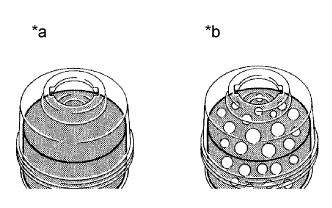
Text in Illustration *a Normal *b Abnormal Check for foaming or emulsification.
Especially, if the system has to be bled twice because of foaming or emulsification, check for fluid leakage in the system.
-
Check the fluid level.
-
-
CHECK POWER STEERING FLUID LEAKAGE
-
INSPECT AND ADJUST FRONT WHEEL ALIGNMENT (INDEPENDENT FRONT SUSPENSION)
-
INSPECT AND ADJUST FRONT WHEEL ALIGNMENT (RIGID FRONT SUSPENSION)