EXHAUST PIPE (w/ DPF) INSTALLATION

-
INSTALL LOWER NO. 2 EXHAUST PIPE PROTECTOR
-
Install the lower No. 2 exhaust pipe protector with the 2 bolts.
- Torque:
- 11 N*m { 107 kgf*cm, 8 ft.*lbf }
-
-
INSTALL LOWER NO. 1 EXHAUST PIPE PROTECTOR
-
Install the lower No. 1 exhaust pipe protector with the 3 bolts.
- Torque:
- 11 N*m { 107 kgf*cm, 8 ft.*lbf }
-
-
INSTALL EXHAUST GAS TEMPERATURE SENSOR
-
Using a union nut wrench 14 mm, install the exhaust gas temperature sensor.
- Torque:
- 30 N*m { 306 kgf*cm, 22 ft.*lbf }
-
Using a union nut wrench 14 mm, install the No. 2 exhaust gas temperature sensor.
- Torque:
- 30 N*m { 306 kgf*cm, 22 ft.*lbf }
-
Using a union nut wrench 14 mm, install the No. 3 exhaust gas temperature sensor.
- Torque:
- 30 N*m { 306 kgf*cm, 22 ft.*lbf }
-
-
INSTALL FRONT EXHAUST PIPE ASSEMBLY
-
Hang the front exhaust pipe assembly with the 2 No. 4 exhaust pipe supports.
-
Install the new gasket onto the front exhaust pipe assembly.
-
Install the front exhaust pipe assembly with the 3 new nuts.
- Torque:
- 63 N*m { 642 kgf*cm, 46 ft.*lbf }
-
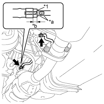
Text in Illustration *1 Spool *a Matchmarks *b 4 to 10 mm Connect the 2 exhaust pipe air hoses with the 2 new clips.
Note
-
Align the matchmarks and insert the front exhaust pipe assembly into the air hose until the air hose contacts the spool of the front exhaust pipe assembly.
-
Install the clip approximately 4 mm (0.157 in.) to 10 mm (0.394 in.) from the tip of the air hose.
-
Make sure there is no slack in the air hose, and that it is not twisted, kinked, or creased.
-
Make sure not to damage the inner or outer surfaces of the air hose when installing it.
-
If the air hose is damaged in any way, replace it with a new one.
-
-
Connect the No. 3 exhaust gas temperature sensor connector.
-
Connect the exhaust gas temperature sensor connector.
-
Install the heat insulator bracket with the bolt.
- Torque:
- 18 N*m { 184 kgf*cm, 13 ft.*lbf }
-
-
INSTALL FRONT NO. 2 EXHAUST PIPE ASSEMBLY (w/ Front No. 2 Exhaust Pipe)
-
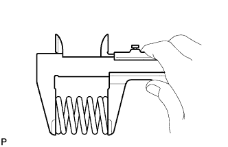
Using a vernier caliper, measure the free length of the compression springs.
Minimum length 40.5 mm (1.594 in.*lbf) If the length is not as specified, replace the compression spring.
-
Hang the front No. 2 exhaust pipe assembly with the No. 4 exhaust pipe support.
-
Install the new gasket onto the front exhaust pipe assembly.
-
Install the front No. 2 exhaust pipe assembly with the 2 compression springs and 2 bolts.
- Torque:
- 43 N*m { 438 kgf*cm, 32 ft.*lbf }
-
-
INSTALL CENTER EXHAUST PIPE ASSEMBLY (for Short and Long Wheelbase)
-
Using a vernier caliper, measure the free length of the compression springs.
Minimum length 40.5 mm (1.594 in.*lbf) If the length is not as specified, replace the compression spring.
-
Hang the center exhaust pipe assembly with the 2 No. 4 exhaust pipe supports.
-
Install the new gasket onto the front exhaust pipe assembly.
-
Install the center exhaust pipe assembly with the 2 compression springs and 2 bolts.
- Torque:
- 43 N*m { 438 kgf*cm, 32 ft.*lbf }
Tech Tips
After the installation, check that the gaps between the flanges of the exhaust manifold converter subassembly and front exhaust pipe assembly are consistent front-to-rear and left-to-right.
-
-
INSTALL CENTER EXHAUST PIPE ASSEMBLY (for Super Long and Extra Super Long Wheelbase)
-
Using a vernier caliper, measure the free length of the compression springs.
Minimum length 40.5 mm (1.594 in.*lbf) If the length is not as specified, replace the compression spring.
-
Hang the center exhaust pipe assembly with the 2 No. 4 exhaust pipe supports.
-
Install the new gasket onto the front exhaust pipe assembly.
-
Install the center exhaust pipe assembly with the 2 new nuts and 2 bolts.
- Torque:
- 43 N*m { 438 kgf*cm, 32 ft.*lbf }
Tech Tips
After the installation, check that the gaps between the flanges of the exhaust manifold converter subassembly and front exhaust pipe assembly are consistent front-to-rear and left-to-right.
-
-
INSTALL TAIL EXHAUST PIPE ASSEMBLY
-
Install the new gasket onto the center exhaust pipe assembly.
-
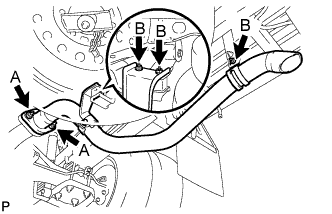
Install the tail exhaust pipe assembly with the 5 new nuts and 3 bolts.
- Torque:
- for nut A
- 43 N*m { 438 kgf*cm, 32 ft.*lbf }
- for nut B
- 19 N*m { 194 kgf*cm, 14 ft.*lbf }
-
-
INSTALL AIR FUEL RATIO SENSOR
-
Using SST, install the air fuel ratio sensor to the front exhaust pipe.
- SST
- 09224-00010
- Torque:
- without SST
- 44 N*m { 449 kgf*cm, 32 ft.*lbf }
- with SST
- 39 N*m { 398 kgf*cm, 29. ft.*lbf }
Tech Tips
-
Use a torque wrench with a fulcrum length of 30 cm (11.8 in.). When using a torque wrench with a fulcrum length that is not 30 cm (11.8 in.), calculate the torque specification for the torque wrench and SST based on the "without SST" torque specification Click here.
-
Make sure SST and the wrench are connected in a straight line.
-
Connect the air fuel ratio sensor connector and engage the wire harness clamp.
Tech Tips
Make sure that the part of the wire harness labeled A is as shown in the illustration.
-
-
INSPECT FOR EXHAUST GAS LEAK