TURBOCHARGER REASSEMBLY

-
INSTALL TURBINE HOUSING
-
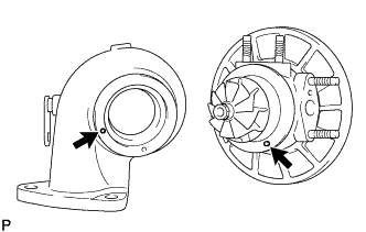
Align the pin of the turbine housing with the pin hole of the bearing housing.
-
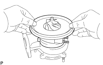
Install the bearing housing to the turbine housing.
Note
Install the bearing housing straight, and be careful not to damage the turbine wheel.
-
-
INSTALL V BAND
-
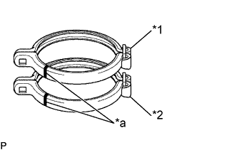
Text in Illustration *1 Old V Band *2 New V Band *a Matchmark Place a new and old (used) V bands in line, then reprint the matchmark position on the old V band to the new one.
-
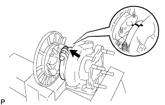
Align the matchmarks on the new V band, turbine housing and bearing housing, and temporarily install a new bolt and nut.
Tech Tips
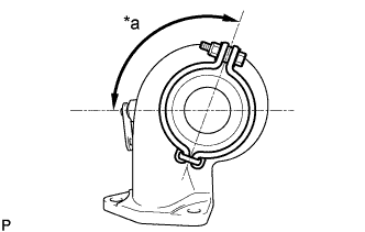
If the matchmarks erased, install the V band as shown in the illustration.
Text in Illustration *a Approx. 125° -
Text in Illustration *a 60° Tighten the V band nut lightly.
-
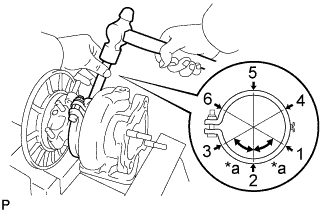
Using a brass bar and hammer, hit the V band for 2 or 3 times lightly at each place in the order of 1 through 6 as shown in the illustration.
-
Tighten the nut with the specified torque.
- Torque:
- 5.0 N*m { 51 kgf*cm, 44 in.*lbf }
-
Using a brass bar and hammer, hit the V band for 2 or 3 times lightly at each place in the order of 1 through 6 as shown in the illustration.
-
Tighten the nut completely.
- Torque:
- 5.0 N*m { 51 kgf*cm, 44 in.*lbf }
-
-
INSTALL COMPRESSOR HOUSING
-
Text in Illustration *1 Seal Packing In case of reusing the compressor housing and bearing housing:
-
Apply seal packing to the bearing housing, as shown in the illustration.
Seal packing Toyota Genuine Seal Packing Black, Three Bond 1207B or equivalent Seal packing applying width 1.2 - 1.6 mm (0.047 - 0.063 in.) Note
Avoid applying an excessive amount to the surface.
-
Install a nozzle that has a cut of a 1.6 mm (0.063 in.) opening.
-
Parts must be assembled within 5 minutes after the application. Otherwise, the material must be removed and reapplied.
-
Immediately remove the nozzle from the tube and reinstall the cap.
-
-
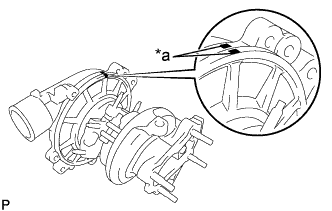
Text in Illustration *a Matchmark Align the matchmarks on the compressor housing and bearing housing, and install them.
Note
-
Do not interfere the impeller wheel with the compressor housing.
-
Check that the turbine shaft turns smoothly.
-
-
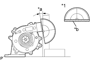
Text in Illustration *1 Protractor Steel Square *a Approx. 10° *b Cut Using a steel square and protractor, check the installation angle as shown in the illustration.
-
Install the 5 bolts.
- Torque:
- 5.2 N*m { 53 kgf*cm, 46 in.*lbf }
-
-
In case of using a new compressor housing and/or bearing housing:
-
Temporarily install the compressor housing on the bearing housing as shown in the illustration.
-
Place matchmarks on the compressor housing and bearing housing.
-
Remove the compressor housing.
-
Reinstall the compressor housing according to the step (a).
-
-
-
INSTALL ACTUATOR AND LINK ASSEMBLY
-
Using SST, apply pressure to the actuator.
- SST
- 09992-00242
Note
Never apply more than 147 kPa (1.50 kgf*cm2, 21.2 psi) of pressure to the actuator.
-
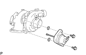
Install the actuator with the 2 bolts and E-ring.
- Torque:
- 8.0 N*m { 82 kgf*cm, 71 in.*lbf }
-
Remove SST.
-
Connect the actuator hose.
-
-
ADJUST ACTUATOR PUSH ROD STROKE
Tech Tips
Adjust the actuator push rod stroke is decided by the plate washer as shown in the illustration.
Note
Never apply more than 147 kPa (1.50 kgf*cm2, 21.2 psi) of pressure to the actuator.
-
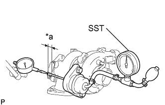
Text in Illustration *a Push Rod Stroke Set the dial indicator as shown in the illustration.
-
Using SST, apply 114 kPa (1.16 kgf*cm2, 16.4 psi) of pressure to the actuator, and measure the push rod stroke.
- SST
- 09992-00242
-
Select the plate washer according to the table below.
Stroke measurement [mm (in.)] Required plate washer thickness [mm (in.)] 1.20 - 1.70 (0.0472 - 0.0669) - 1.71 - 2.20 (0.0673 - 0.0866) 0.5 (0.020) 2.21 - 2.70 (0.0870 - 0.1063) 1.0 (0.039) 2.71 - 3.20 (0.1067 - 0.1260) 1.5 (0.059) 3.21 - 3.70 (0.1264 - 0.1457) 2.0 (0.079) 3.71 - 4.20 (0.1461 - 0.1850) 2.5 (0.098) 4.21 - 4.70 (0.1657 - 0.1850) 3.0 (0.118) 4.71 - 5.20 (0.1854 - 0.2047) 3.5 (0.138) 5.21 - 5.70 (0.2051 - 0.2244) 4.0 (0.157) 5.71 - 6.20 (0.2248 - 0.2441) 4.5 (0.177) 6.21 - 6.70 (0.2445 - 0.2638) 5.0 (0.197) 6.71 - 7.20 (0.2642 - 0.2827) 5.5 (0.217) 7.21 - 7.70 (0.2839 - 0.3031) 6.0 (0.236) 7.71 - 8.20 (0.3035 - 0.3228) 6.5 (0.256) Note
-
Use a combination of plate washers of 0.5 mm (0.020 in.), 1.0 mm (0.039 in.) and 3.0 mm (0.118 in.) thickness to achieve the required thickness.
-
Use the same thickness of the plate washer for the 2 locations between the actuator and compressor housing.
-
If the plate washer thickness exceeds 3.5 mm (0.138 in.), replace the actuator installation bolts with the bolts from the kit part.
-
-
Install the 2 washers and actuator (See step 4).
-
Using SST, apply 119 kPa (1.21 kgf*cm2, 17.2 psi) of pressure to the actuator, and install the selected plate washers between the actuator and compressor housing with the 2 bolts.
- SST
- 09992-00242
- Torque:
- 8.0 N*m { 82 kgf*cm, 71 in.*lbf }
-
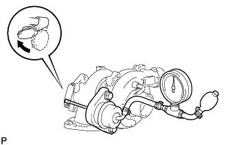
Text in Illustration *a Push Rod Stroke Using SST, apply 113 kPa (1.13 kgf*cm2, 16.1 psi) of pressure to the actuator, and measure the actuator push rod stroke.
- SST
- 09992-00242
Standard stroke 1.20 - 1.70 mm (0.0472 - 0.0669 in.) If the stroke is outside specifications, select the plate washers again.
-
Connect the actuator hose.
-
Remove SST.
-
Apply yellow paint from the actuator bolts to the actuator bracket (Means that the actuator has been installed correctly).
-