VACUUM SWITCHING VALVE (w/ DPF) INSPECTION
-
INSPECT NO. 1 VACUUM SWITCHING VALVE ASSEMBLY (for Swirl Control Valve)
-
Check the resistance of the vacuum switching valve.
-
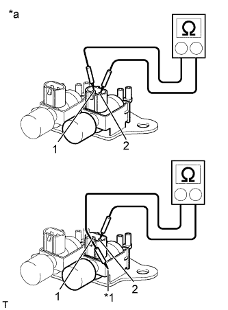
Text in Illustration *1 Body *a Component without harness connected
(No. 1 vacuum switching valve)
Measure the resistance according to the value(s) in the table below.
Standard Resistance Tester Connection Condition Specified Condition 1 - 2 20°C (68°F) 33 to 39 Ω 1 - Body ground Always 10 kΩ or higher 2 - Body ground If the result is not as specified, replace the No. 1 vacuum switching valve assembly.
-
-
Check the operation of the vacuum switching valve.
-
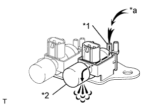
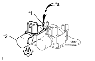
Text in Illustration *1 Port E *2 Filter *a Air Check that air flows from port E to the filter.
If the result is not as specified, replace the No. 1 vacuum switching valve assembly.
-
-
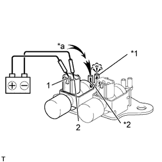
Apply battery voltage across the terminals.
-
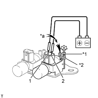
Text in Illustration *1 Port F *2 Port E *a Air Check that air flows from port E to port F.
If the result is not as specified, replace the No. 1 vacuum switching valve assembly.
-
-
-
INSPECT NO. 2 VACUUM SWITCHING VALVE ASSEMBLY (for Swirl Control Valve)
-
Check the resistance of the vacuum switching valve.
-
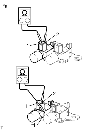
Text in Illustration *1 Body *a Component without harness connected
(No. 2 vacuum switching valve)
Measure the resistance according to the value(s) in the table below.
Standard Resistance Tester Connection Condition Specified Condition 1 - 2 20°C (68°F) 33 to 39 Ω 1 - Body ground Always 10 kΩ or higher 2 - Body ground If the result is not as specified, replace the No. 2 vacuum switching valve assembly.
-
-
Check the operation of the vacuum switching valve.
-
Text in Illustration *1 Port E *2 Filter *a Air Check that air flows from port E to the filter.
If the result is not as specified, replace the No. 2 vacuum switching valve assembly.
-
-
Apply battery voltage across the terminals.
-
Text in Illustration *1 Port F *2 Port E *a Air Check that air flows from port E to port F.
If the result is not as specified, replace the No. 2 vacuum switching valve assembly.
-
-