INTAKE SYSTEM (w/o DPF) ON-VEHICLE INSPECTION

-
CHECK INTAKE MANIFOLD
-
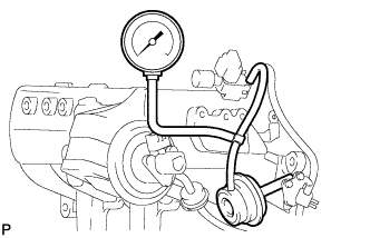
Connect a vacuum gauge between the control valve and VSV.
-
Warm up the engine.
-
Measure the vacuum.
Standard vacuum Engine Condition VSV Condition Specified Condition Normal engine speed ON Approx. 35 kPa (263 mmHg, 10.35 in.Hg) 3,000 rpm or more OFF 0 kPa (0 mmHg, 0 in.Hg)
-
-
CHECK INTAKE AIR SYSTEM
-
Check for leakage or clogging between the air cleaner housing and turbocharger inlet, and between the turbocharger outlet and cylinder head.
Condition Operation Clogged air cleaner Clean or replace Collapsed or deformed hoses Repair or replace Leakage from connections Check each connection and repair Cracks in components Check and replace
-
-
CHECK EXHAUST SYSTEM
-
Check for leakage or clogging between the cylinder head and turbocharger inlet, and between the turbocharger outlet and exhaust pipe.
Condition Operation Deformed components Repair or replace Foreign matter in passages Remove Leakage from components Repair or replace Cracks in components Check and replace
-
-
CHECK BOOST PRESSURE
-
Connect the intelligent tester to the DLC3.
-
Start the engine and turn the tester ON.
-
Warm up the engine.
Tech Tips
Be sure to perform the inspection when the engine coolant temperature is between 75 and 90°C (167 and 194°F).
-
Enter the following menus: Powertrain / Engine and ECT / Data List / All Data.
-
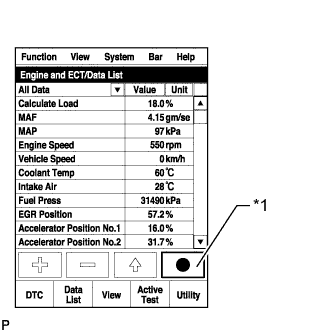
Text in Illustration *1
Snapshot Record Button Take a snapshot of the Data List items with the intelligent tester shown in the illustration.
Tech Tips
-
Graphs can be displayed by transferring the stored snapshot from the tester to a PC. Intelligent Viewer must be installed on the PC.
-
The condition of the turbocharger can be determined by fully depressing the accelerator pedal while driving at 15 km/h (9 mph) in 2nd gear to accelerate the vehicle (obey all laws and regulations, and pay attention to driving conditions while driving the vehicle), and then comparing MAP with Target Booster Pressure at an engine speed of 3000 rpm.
-
-
Compare MAP with Target Booster Pressure.
Standard MAP is within 30 kPa of Target Booster Pressure when accelerating with accelerator pedal fully depressed. Tech Tips
-
The specification above denotes the difference between the absolute pressure values.
-
If the driving inspection using the intelligent tester above cannot be performed (e.g. due to road conditions), perform the following inspection.
-
Warm up the engine.
Tech Tips
Be sure to perform the inspection when the engine coolant temperature is between 75 and 90°C (167 and 194°F).
-
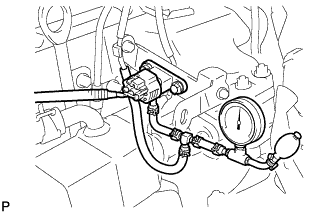
Using a 3-way connector, connect SST (turbocharger pressure gauge) between the diesel turbo pressure sensor (manifold absolute pressure sensor) and the gas filter.
- SST
- 09992-00242
-
Fully apply the parking brake and chock the 4 wheels.
-
While depressing the clutch pedal, fully depress the accelerator pedal. Measure the boost pressure at maximum engine speed (approximately 4450 rpm).
Standard Pressure (Gauge Pressure) 10 to 40 kPa (0.10 to 0.41 kgf*cm2, 1.4 to 5.8 psi) If the pressure is lower than the standard, the following problems may be present.
-
The intake system or exhaust system has leakage or blockage.
-
The turbocharger sub-assembly or turbo motor driver is malfunctioning.
-
The EGR valve does not close.
-
The diesel throttle body does not open.
-
The vacuum hose connected to the diesel turbo pressure sensor (manifold absolute pressure sensor) is cracked or disconnected.
-
The mass air flow meter is malfunctioning.
-
A fuel injector is malfunctioning.
If the pressure is higher than the standard, check the turbocharger and/or boost control components (turbo motor driver, pressure sensor, vacuum hose, wire harness, etc.).
-
-
-
Chart showing the suspected trouble areas when the pressure is lower than the standard.
Tech Tips
-
○: If a problem listed in the leftmost column of the chart exists, or if the part in the leftmost column of the chart has a malfunction, the value of the Data List item in the uppermost row of the chart will meet the conditions shown in the row labeled "Value which represents a malfunction".
-
The values in the chart are applicable when the engine coolant temperature is between 75 and 90°C (167 and 194°F).
-
The values in the chart are valid in an area with an absolute atmospheric pressure higher than 95 kPa. (Standard atmospheric pressure is 101 kPa. Atmospheric pressure decreases by 1 kPa for every 100 m increase in altitude, and is also affected by the current weather conditions.)
-
When the altitude increases, atmospheric pressure and MAP decrease.
Item MAP
(Absolute pressure inside intake manifold)
MAF
(Intake air flow rate)
Accel Position Actual Throttle Position Actual EGR Valve Pos.
or
EGR Lift Sensor Volt %
EGR Close Lrn. Status
(EGR valve fully closed position learning status)
Fuel Pressure Injection Feedback Val #1 (to #4) Values taken from an actual normal vehicle
*1
- w/ EGR Cooler Bypass Valve:
115 to 150 g/sec
99 % or more 0% w/ EGR Cooler Bypass Valve:
Actual EGR Valve Pos. is
0%
OK - -3 to +3 mm3/st
w/o EGR Cooler Bypass Valve:
115 to 145 g/sec
w/o EGR Cooler Bypass Valve:
EGR Lift Sensor Volt % value is
20 to 40 %
Values which represent a malfunction
*1
MAP is below Target Booster Pressure by 30 kPa or more MAF is less than 115 g/sec. Accel Position is not fully depressed position
*2
Actual Throttle Position is not fully open position w/ EGR Cooler Bypass Valve:
Actual EGR Valve Pos. is not valve fully closed position
*3
NG
(Determined after performing learning)
Fuel Pressure is below Target Common Rail Pressure by 10 MPa or more (Check while condition steady) Outside of above range w/o EGR Cooler Bypass Valve:
EGR Valve Lift Sensor Volt % is not within 20 to 40 %
*3
Turbocharger ○ ○ - - - - - - EGR valve does not close or has problem with movement ○ ○ - - ○
(Problem with EGR valve movement)
*4
○
(EGR valve does not close)
*4
- - Problem with diesel throttle movement ○
(Intake airflow decreases)
○ - ○ - - - - Accelerator pedal cannot be fully depressed or problem with accelerator pedal position sensor exists - ○ ○ - - - - - Intake air system leakage or blockage ○ ○ - - - - - - Exhaust gas leakage before turbocharger or blockage ○ ○ - - - - - - Manifold absolute pressure sensor ○ ○ - - - - - - Manifold absolute pressure sensor hose is disconnected ○ ○ - - - - - - Mass air flow meter sub-assembly - ○ - - - - - - Fuel system (injector, supply pump or common rail) ○ ○ - - - - ○
(Fuel injector leakage, decrease in pressure discharge valve relief pressure or valve is stuck)
○
*5
Tech Tips
-
*1: These values are measured when the transmission is in 2nd gear, the accelerator pedal is fully depressed, the vehicle is accelerating, and the engine speed is 3000 rpm.
-
*2: The Accel Position is the accelerator opening angle (%) for engine control use. The value indicates around 100 % when the accelerator pedal fully depressed. If the value does not indicate around 100 % when the accelerator pedal fully depressed, the accelerator pedal position sensor circuit or the pedal itself is malfunctioning. When the MIL is illuminated, even with the accelerator pedal fully depressed and an Accel Position of below 70%, it means the fail-safe is restricting the accelerator.
-
*3: The Data List items indicated on the tester differ according to vehicle model and engine type. If the Actual EGR Valve Pos. is not available but the EGR Lift Sensor Volt %*6is available, check that the EGR Lift Sensor Volt % is always following the Target EGR Position value. The EGR valve may be malfunctioning if the value is stuck or does not fluctuate smoothly. However, in some cases the EGR valve may be malfunctioning even if the Actual EGR Valve Pos. and/or EGR Lift Sensor Volt % values are normal. Inspect the EGR valve for any defects (deposits, valve stuck, poor movement, etc.) if necessary.
On engines without EGR cooler bypass valves, the EGR operation is performed during vehicle acceleration and a small amount of EGR gas is introduced to the cylinder.
-
*4: DTC P0400, P2BAB, or P2BAC may be stored at this time. If the actual EGR valve position follows the target EGR valve position slowly, a feeling of hesitation may occur.
-
*5: If Injection Feedback Val # of a cylinder is not within -3 to +3 mm3/st, the corresponding cylinder may have a malfunction (injector or compression). However, in some cases the cylinder may be malfunctioning even if the value is within -3 to +3 mm3/st because these values are injection volume correction values calculated by the ECM at the engine idling and not correction values for the high engine load condition related to the boost pressure control and engine output performance.
-
*6: The Data List item EGR Lift Sensor Volt % is calculated from the EGR valve position sensor output voltage. Value is 0 to 5 V converted to 0 to 100%.
Reference:
Fully closed: around 15%
Fully open: around 80%
Sensor output characteristics differ according to type of EGR valve. On engines with EGR cooler bypass valves, the output characteristics are opposite to the reference values above.
-
-
-
INSPECT MANIFOLD ABSOLUTE PRESSURE SENSOR
-
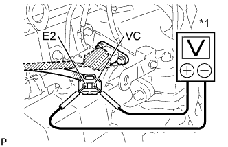
Text in Illustration *1 Voltmeter Inspect the power source voltage.
-
Disconnect the pressure sensor connector.
-
Turn the ignition switch ON.
-
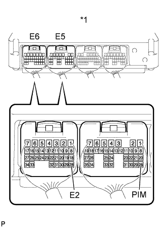
Measure the voltage between terminals 3 (VC) and 1 (E2) of the wire harness side connector.
Standard voltage 4.75 to 5.25 V If the result is not as specified, inspect the wire harness or ECM Click here.
-
Turn the ignition switch OFF.
-
Connect the pressure sensor connector.
-
-
Text in Illustration *1 ECM Check the power supply.
-
Turn the ignition switch ON.
-
Disconnect the vacuum hose from the pressure sensor.
-
Connect a voltmeter to terminals E5-28 (PIM (+)) and E6-28 (E2 (-)) of the ECM, and measure the output voltage at ambient atmospheric pressure.
-
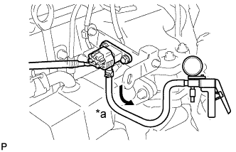
Text in Illustration *a Vacuum Apply a vacuum to the pressure sensor in 13.3 kPa (100 mmHg, 3.94 in.Hg) increments until the pressure reaches 40.0 kPa (300 mmHg, 11.81 in.Hg). Measure the increase in voltage for each increment.
Standard voltage Applied Vacuum Voltage Decrease -13.3 kPa (-100 mmHg, -3.94 in.Hg) 0.8 to 1.1 V -26.6 kPa (-199 mmHg, -7.85 in.Hg) 0.6 to 1.0 V -40 kPa (-300 mmHg, -11.81 in.Hg) 0.4 to 0.8 V If the result is not as specified, replace the manifold absolute pressure sensor.
-
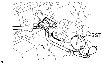
Text in Illustration *a Pressure Using SST (turbocharger pressure gauge), apply pressure to the pressure sensor in 19.6 kPa (0.20 kgf*cm2, 2.84 psi) increments until the pressure reaches 98.0 kPa (1.00 kgf*cm2, 14.2 psi). Measure the increase in voltage for each increment.
- SST
- 09992-00242
Standard voltage Applied Pressure Voltage Decrease 19.6 kPa (0.20 kgf*cm2, 2.84 psi)
1.2 to 1.5 V 39.2 kPa (0.40 kgf*cm2, 5.69 psi)
1.5 to 1.8 V 58.8 kPa (0.60 kgf*cm2, 8.53 psi)
1.8 to 2.1 V 78.5 kPa (0.80 kgf*cm2, 11.4 psi)
1.9 to 2.2 V 98.0 kPa (1.00 kgf*cm2, 14.2 psi)
2.1 to 2.4 V If the result is not as specified, replace the manifold absolute pressure sensor.
-
-
-
CHECK MOTOR FOR TURBOCHARGER CONTROL OPERATION
CAUTION:
-
Wear protective gloves to prevent injuries and burns when checking the turbocharger.
-
The engine compartment becomes hot when the engine is running.
-
Remove the No. 1 turbo insulator and No. 1 exhaust manifold heat insulator Click here.
-
Check the stroke.
Note
Make sure the DC motor's connectors are properly installed.
-
Turn the ignition switch ON and OFF.
-
Check the DC motor's operation. Check that the motor rod stroke is as shown in A to D in the illustration below.
-
After the DC motor operates, visually check that the vane activation link contacts the fully closed stopper.
Note
Never loosen or tighten the fully closed stopper's lock nut.
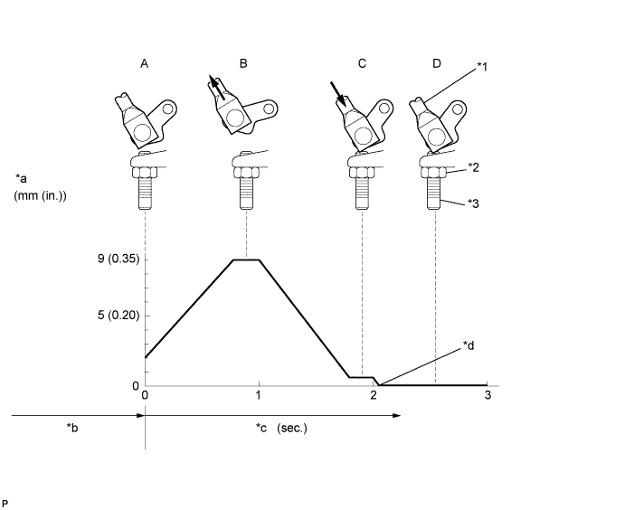
Text in Illustration *1 Motor Rod *2 Lock Nut *3 Fully Closed Stopper - - *a Motor Rod Stroke *b Ignition Switch ON *c Ignition Switch OFF Time *d Fully Closed Stopper Contact If the result is not as specified, check the ECM Click here and turbo motor driver Click here.
-
-
-
CHECK TURBO MOTOR DRIVER
-
Check the voltage of the turbo motor driver.
-
Turn the ignition switch ON.
-
Measure the voltage of the turbo motor driver.
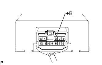
Standard voltage Tester Connection Specified Condition 3 (+B) - Body ground 9 to 14 V If the voltage is not as specified, refer to the following procedures Click here.
-
-
Check the resistance of the wire harness side connector.
-
Turn the ignition switch OFF.
-
Disconnect the turbo motor driver connector.
-
Measure the resistance of the turbo motor driver connector.
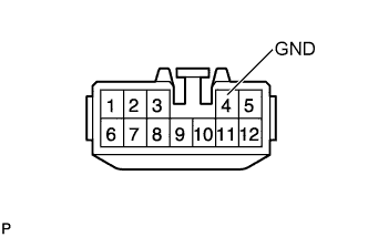
Standard resistance Tester Connection Specified Condition 4 (GND) - Body ground Below 1 Ω If the resistance is not as specified, refer to the following procedures Click here.
-
-
Connect the turbo motor driver connector.
-
Check the turbo motor signal.
-
Connect an oscilloscope to the terminals of the ECM.
-
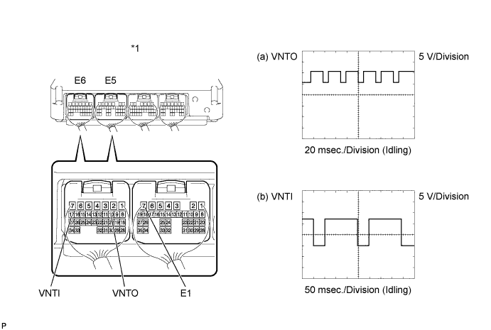
While idling the engine, check the waveform of the ECM.
Standard condition ECM Terminal (a) Between E6-10 (VNTO) and E5-7 (E1)
(b) Between E6-17 (VNTI) and E5-7 (E1)
Tester Range (a) 5 V/Division, 20 msec./Division
(b) 5 V/Division, 50 msec./Division
Specified Condition Idling with warm engine If the result is not as specified, replace the turbo motor driver.
Tech Tips
The waveform varies depending on the turbocharger operation.
Text in Illustration *1 ECM - -
-
-