EMISSION CONTROL SYSTEM ECM Power Source Circuit
DESCRIPTION
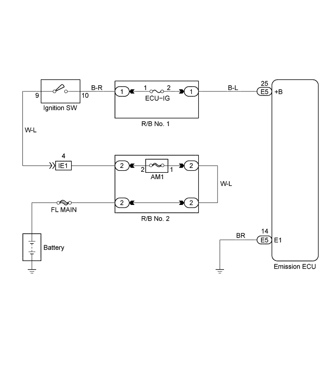
When the ignition switch is turned ON, battery positive voltage is applied to the coil, supplying power to the terminal +B of the emission ECU.
WIRING DIAGRAM
INSPECTION PROCEDURE
PROCEDURE
-
CHECK EMISSION CONTROL ECU
-
Turn the ignition switch ON.
-
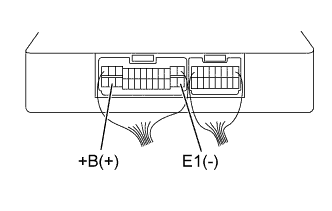
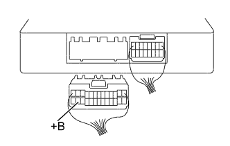
Measure the voltage between terminals +B and E1 of the emission ECU. Click here
VOLTAGE 9 - 14 V
OK 
GO TO PROBLEM SYMPTOMS TABLE Click here
NG 
-
-
CHECK WIRE HARNESS OR CONNECTOR (ECU GROUND)
-
Disconnect the battery negative cable.
-
Disconnect the emission ECU connector.
-
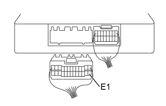
Check for open between terminal E1 of the emission ECU E1 connector and body ground Click here.
RESISTANCE 1 Ω or less
NG
REPAIR OR REPLACE WIRE HARNESS OR CONNECTOR
OK
-
-
CHECK FUSE (ECU-IG)
-
Remove the ECU-IG fuse from the R/B NO.1.
-
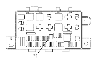
Text in Illustration *1 ECU-IG Check the continuity of the ECU-IG fuse.
OK CONTINUITY
NG
REPLACE FUSE (ECU-IG)
OK
-
-
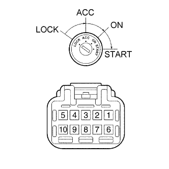
CHECK IGNITION OR STARTER SWITCH ASSEMBLY
-
Remove the lower finish panel.
-
Disconnect the ignition switch connector.
-
Check the continuity between the terminals shown below.
OK Switch Position Terminal No. to continuity LOCK - - ACC 4 - 9 - ON 4 - 9 - 10 5 - 8 START 3 - 9 - 10 5 - 8
NG
REPLACE IGNITION OR STARTER SWITCH ASSEMBLY
OK
-
-
CHECK WIRE HARNESS (EMISSION ECU - IGNITION SWITCH)
-
Remove the lower finish panel.
-
Disconnect the ignition switch connector.
-
Disconnect the emission ECU connector.
-
Check the continuity between terminals 2 of the ignition switch harness connector and +B of the ECU connector Click here.
RESISTANCE 1 Ω or less -
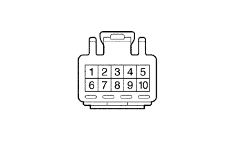
Check for short between terminals 2 of the ignition switch harness connector and +B of the ECU connector Click here.
RESISTANCE 1 MΩ or more
NG
REPAIR OR REPLACE WIRE HARNESS OR CONNECTOR
OK
-
-
CHECK FUSE (AM1)
-
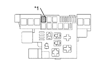
Text in Illustration *1 AM1 Remove the AM1 fuse from the R/B No.2.
-
Check the continuity of the AM1 fuse.
OK CONTINUITY
NG
REPLACE FUSE (AM1)
OK 
REPAIR OR REPLACE WIRE HARNESS OR CONNECTOR (IGNITION SWITCH-BATTERY)
-