EMISSION CONTROL SYSTEM Pre-heating Control Circuit
DESCRIPTION
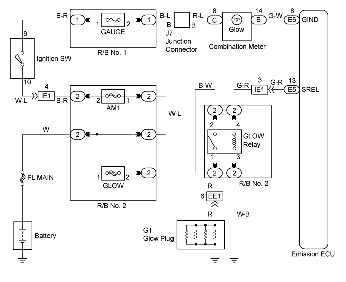
When the ignition switch turns ON, the emission ECU calculates the glow indicator lighting time/heating correspondings to the coolant temperature at that time and turns ON the glow indicator light/glow plug relay. As the ceramics is used for a glow plug material, the current control is not performed.

WIRING DIAGRAM
INSPECTION PROCEDURE
PROCEDURE
-
CHECK GLOW INDICATOR LIGHT
-
Turn the ignition switch ON.
-
Check that the glow indicator lights up.
OK GLOW INDICATOR LIGHTS UP FOR 0.5 SEC. OR MORE
OK 
GO TO STEP
NG 
-
-
CHECK EMISSION CONTROL ECU (EMISSION ECU-BODY GROUND)
-
Disconnect the emission ECU connector.
-
Turn the ignition switch ON.
-
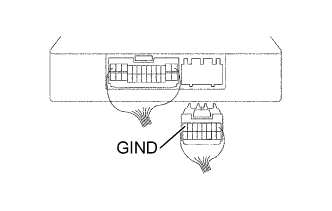
Measure the voltage between terminal GIND of the emission ECU connector and body ground Click here.
VOLTAGE 9 - 14 V
OK
CHECK AND REPLACE EMISSION CONTROL ECU Click here
NG
-
-
CHECK FUSE (GAUGE)
-
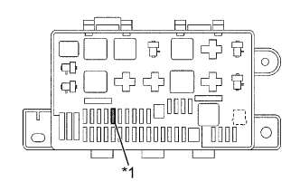
Text in Illustration *1 GAUGE Remove the GAUGE fuse.
-
Measure the continuity of the GAUGE fuse.
OK CONTINUITY
NG
REPLACE FUSE (GAUGE)
OK
-
-
CHECK GLOW INDICATOR LIGHT BULB
NG
REPLACE BULB
OK 
REPAIR OR REPLACE WIRE HARNESS OR CONNECTOR (COMBINATION METER AND EMISSION ECU, COMBINATION METER - GAUGE FUSE) Click here
-
CHECK INDICATOR LIGHTING TIME AND AFTER GLOW TIME
NG
CHECK AND REPLACE EMISSION CONTROL ECU Click here
OK
-
CHECK DTC
-
Are there any DTC being output?
YES
GO TO RELEVANT DTC CHART Click here
NO
-
-
INSPECT GLOW PLUG RELAY ASSEMBLY
NG
REPLACE GLOW PLUG RELAY ASSEMBLY
OK
-
CHECK EMISSION CONTROL ECU
-
Disconnect the emission ECU connector.
-
Turn the ignition switch to START position.
-
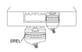
Measure the voltage between terminal SREL of the emission ECU and body ground at cranking Click here.
VOLTAGE 9 - 14 V
NG
CHECK AND REPLACE EMISSION CONTROL ECU Click here
OK
-
-
CHECK WIRE HARNESS OR CONNECTOR (GLOW PLUG RELAY - EMISSION ECU, GLOW PLUG RELAY - BODY GROUND)
-
Remove the GLOW relay from the R/B No.2.
-
Disconnect the emission ECU connector.
-
Check the continuity between terminals SREL of the ECU connector and 3 of the GLOW relay in the R/B No.2 Click here.
RESISTANCE 1 Ω or less -
Check for short between terminals SREL of the ECU connector and 3 of the GLOW relay in the R/B No.2 Click here.
RESISTANCE 1 MΩ or more -
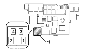
Text in Illustration *1 GLOW Relay Check the continuity between 3 of the GLOW relay in the R/B No.2 and the body ground Click here.
RESISTANCE 1 Ω or less -
Check the continuity between 3 of the GLOW relay in the R/B No.2 and the body ground Click here.
RESISTANCE 1 MΩ or more
NG
REPAIR OR REPLACE WIRE HARNESS OR CONNECTOR
OK
-
-
CHECK GLOW PLUG ASSEMBLY
-
Check the resistance of the glow plug Click here.
NG
REPLACE GLOW PLUG ASSEMBLY
OK
-
-
INSPECT GLOW PLUG ASSEMBLY
-
Inspect the glow plug installation.
NG
TIGHTEN GLOW PLUG
OK
-
-
CHECK WIRE HARNESS (GLOW PLUG RELAY - GLOW PLUG)
-
Remove the GLOW relay from the R/B No.2.
-
Text in Illustration *1 GLOW Relay Check continuity between the GLOW relay in the R/B No.2 and the glow plug.
RESISTANCE 1 Ω or less -
Check for short between the GLOW relay in the R/B No.2 and the glow plug.
RESISTANCE 1 MΩ or more
NG
REPAIR OR REPLACE WIRE HARNESS OR CONNECTOR
OK
PROCEED TO NEXT CIRCUIT INSPECTION SHOWN IN PROBLEM SYMPTOMS TABLE Click here
-