EMISSION CONTROL SYSTEM, Diagnostic DTC:71

| DTC Code | DTC Name |
|---|---|
| 71 | EGR System Malfunction |
DESCRIPTION
The EGR system recirculates exhaust gas, which is controlled to the proper quantity to suit the driving conditions, into the intake air mixture so as to slow down combustion, reduce the combustion temperature and reduce NOx emissions,
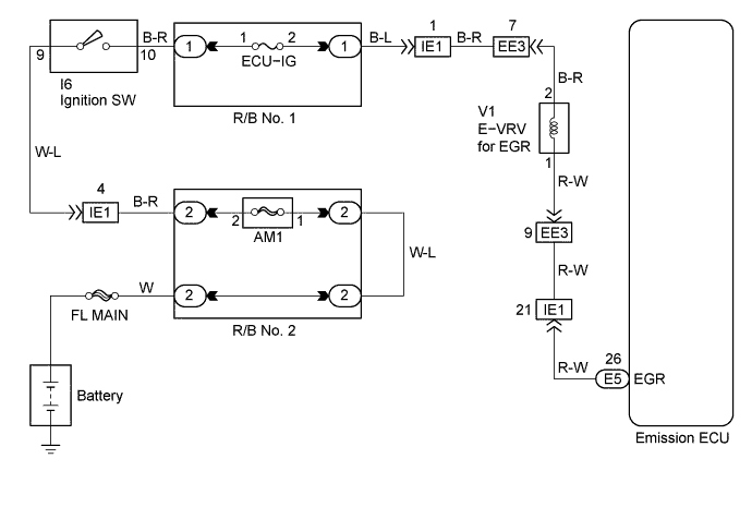
The lift amount of EGR valve is controlled by the vacuum which is regulated by the E-VRV operated by the emission ECU.
Tech Tips
-
Under the following conditions, EGR is cut to maintain driveability.
-
Before the engine is warmed up
-
During deceleration (Diesel throttle valve closed)
-
Light engine load (amount of intake air very small)
-
Engine speed over 4,000 rpm
| DTC No. | DTC Detecting Condition | Trouble Area |
|---|---|---|
| 71 | When abnormal feedback values have been obtained during EGR control operation (2 trip detection logic) |
|
WIRING DIAGRAM
INSPECTION PROCEDURE
PROCEDURE
-
CHECK VACUUM HOSE
-
Check the connection of vacuum hose between the vacuum pump and E-VRV for EGR.
-
Check the connection of vacuum hose between E-VRV for EGR and EGR valve.
NG 
REPAIR OR REPLACE REPAIR OR REPLACE VACUUM HOSE
OK 
-
-
CHECK ELECTRIC EGR CONTROL VALVE ASSEMBLY (OPERATION CHECK)
-
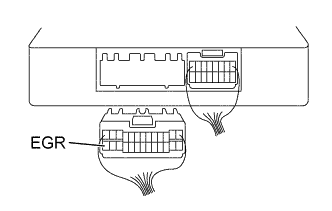
Disconnect the emission ECU connector.
-
Turn the ignition switch ON.
-
Connect terminal EGR of emission ECU connector and body ground (ON).
-
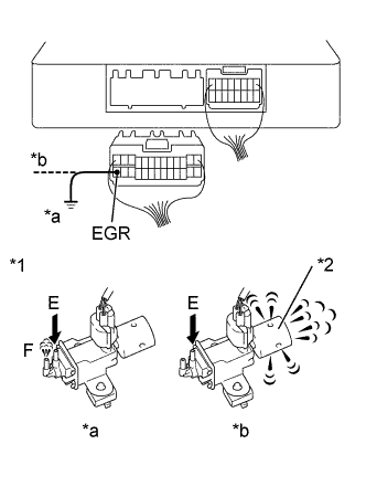
Text in Illustration *1 E-VRV *2 air filter *a ON *b OFF Disconnect terminal EGR of emission ECU connector and body ground (OFF).
Specification E-VRV ON: Air from pipe E flows out through pipe F. E-VRV OFF: Air from pipe E flow is out through air filter.
OK 
CHECK ELECTRIC EGR CONTROL VALVE ASSEMBLY Click here
NG
-
-
INSPECT ELECTRIC EGR CONTROL VALVE ASSEMBLY
NG
REPLACE ELECTRIC EGR CONTROL VALVE ASSEMBLY
OK
-
CHECK WIRE HARNESS AND CONNECTORS (E-VRV - EMISSION ECU)
-
Disconnect the E-VRV connector.
-
Disconnect the emission ECU connector.
-
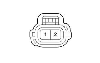
Check the continuity between terminals 1 of the E-VRV harness connector and EGR of the ECU connector Click here.
RESISTANCE 1 Ω or less -
Check for short between terminals 1 of the E-VRV harness connector and EGR of the ECU connector Click here.
RESISTANCE 1 MΩ or more -
To check wire harness for terminal 2 of E-VRV connector, refer to the wiring diagram.
NG
REPAIR OR REPLACE WIRE HARNESS OR CONNECTOR
OK 
CHECK AND REPLACE EMISSION CONTROL ECU Click here
-
-
CHECK ELECTRIC EGR CONTROL VALVE ASSEMBLY
NG
REPLACE ELECTRIC EGR CONTROL VALVE ASSEMBLY
OK
CHECK FOR PROBLEM SYMPTOMS TABLE Click here