EMISSION CONTROL SYSTEM, Diagnostic DTC:43

| DTC Code | DTC Name |
|---|---|
| 43 | Starter Signal Circuit Malfunction |
DESCRIPTION
When the engine is being cranked, the intake air flow is slow, so fuel vaporization is poor. A rich mixture is therefore necessary in order to achieve good startability. While the engine is being cranked, the battery positive voltage is applied to terminal STA of the emission ECU. The starter signal is mainly used to increase the fuel injection volume for the starting injection control and after-start injection control.
| DTC No. | DTC Detecting Condition | Trouble Area |
|---|---|---|
| 43 | No starter signal to emission ECU |
|
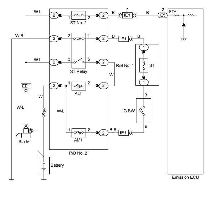
WIRING DIAGRAM
INSPECTION PROCEDURE
Tech Tips
This DTC chart is based on the premise that the engine is being cranked under normal conditions. If the engine does not crank, proceed to the problem symptoms table on page Click here.
PROCEDURE
-
CHECK EMISSION CONTROL ECU
-
Start the engine.
-
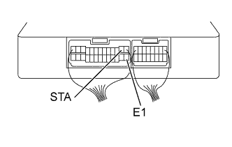
Measure the voltage between terminals STA and E1 of the emission ECU connector during cranking.
VOLTAGE 6.0 V or more
OK 
CHECK FOR PROBLEM SYMPTOMS TABLE Click here
NG 
-
-
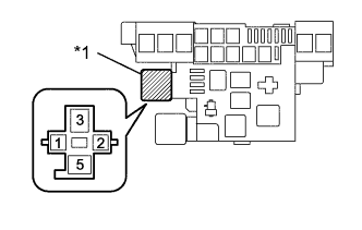
CHECK FUSE (ST NO.2)
-
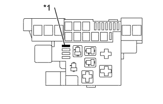
Text in Illustration *1 ST NO.2 Remove the ST NO.2 fuse from the R/B No.2.
-
Check continuity of ST No.2 fuse.
OK CONTINUITY
NG
REPLACE FUSE (ST NO.2)
OK
-
-
CHECK WIRE HARNESS AND CONNECTOR (EMISSION ECU-ST RELAY)
-
Disconnect the battery negative (-) terminal.
-
Remove the starter relay (Marking: ST).
-
Disconnect the emission ECU connector.
Text in Illustration *1 ST Relay -
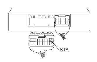
Check the continuity between terminals 3 of the starter relay in the R/B No.2 and STA of the ECU connector Click here.
Note
Do not insert the tester hard in procedure (C), or the holder may be damaged.
RESISTANCE 1 Ω or less
NG
REPAIR OR REPLACE WIRE HARNESS OR CONNECTOR
OK 
CHECK AND REPLACE EMISSION CONTROL ECU Click here
-