EMISSION CONTROL SYSTEM, Diagnostic DTC:42

| DTC Code | DTC Name |
|---|---|
| 42 | Vehicle Speed Sensor Signal Circuit Malfunction |
DESCRIPTION
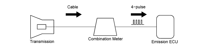
This sensor is mounted in the combination meter. It contains a magnet which is rotated by the speedometer cable.
Turning the reed switch ON and OFF 4 times for every revolution of the speedometer.
It is then transmitted to the ECU. The ECU determines the vehicle speed based on the frequency of these pulse signals.
| DTC No. | DTC Detecting Condition | Trouble Area |
|---|---|---|
| 42 | All conditions below are detected continuously for 8 sec. or more: (a) Vehicle speed signal: 0 km/h (0 mph) (b) Engine speed: 2,000 - 3,200 rpm (c) Engine coolant temp.: 80°C (176°F) or more (d) Load driving |
|
Tech Tips
In the test mode, DTC 42 is output when the vehicle speed is 5 km/h (3 mph) or below.
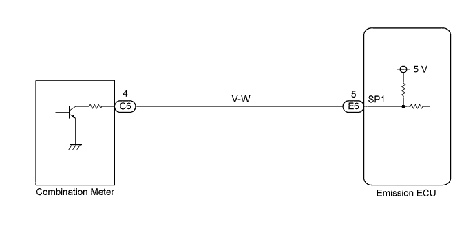
WIRING DIAGRAM
INSPECTION PROCEDURE
PROCEDURE
-
CHECK SPEEDOMETER ASSEMBLY
-
Drive the vehicle and check if the operation of the speedometer in the combination meter is normal.
Tech Tips
The vehicle speed sensor is operating normally if the speedometer display is normal.
NG 
CHECK AND REPLACE SPEEDOMETER ASSEMBLY
OK 
-
-
CHECK SPEEDOMETER SENSOR
-
Shift the shift lever to neutral.
-
Jack up one of the front wheels.
-
Turn the ignition switch ON.
-
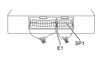

Measure the voltage between terminals SP1 and E1 of the emission ECU when the wheel is turned slowly.
VOLTAGE PULSE GENERATION
NG
REPAIR OR REPLACE WIRE HARNESS OR CONNECTOR (COMBINATION METER-EMISSION ECU)
OK 
CHECK AND REPLACE EMISSION CONTROL ECU Click here
-