EMISSION CONTROL SYSTEM, Diagnostic DTC:41

| DTC Code | DTC Name |
|---|---|
| 41 | Throttle Position Sensor Circuit |
DESCRIPTION
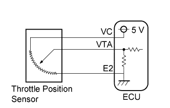
The throttle position sensor is mounted on the injection pump with the bracket and detects the adjusting lever angle. When the adjusting lever is at the idle speed side, a voltage of approximately 3.2 - 4.9 V is applied to the terminal VA of the ECU. When the adjusting lever is opened, the voltage applied to the terminal VA of the ECU increases in proportion to the angle of the adjusting lever and becomes approximately 0.2 - 1.6 V when the adjusting lever is at the maximum speed side. The ECU judges the vehicle driving conditions from these signals input from the terminals VA, and uses them as one of the conditions for deciding the air-fuel ratio correction, power increase correction and fuel-cut control etc.
| DTC No. | DTC Detecting Condition | Trouble Area |
|---|---|---|
| 41 | Open or short in throttle position sensor circuit for 0.5 sec. or more |
|
Tech Tips
When the connector for the throttle position sensor is disconnected, DTC 41 is not displayed. DTC 41 is displayed only when there is an open or short in the VA signal circuit of the throttle position sensor.
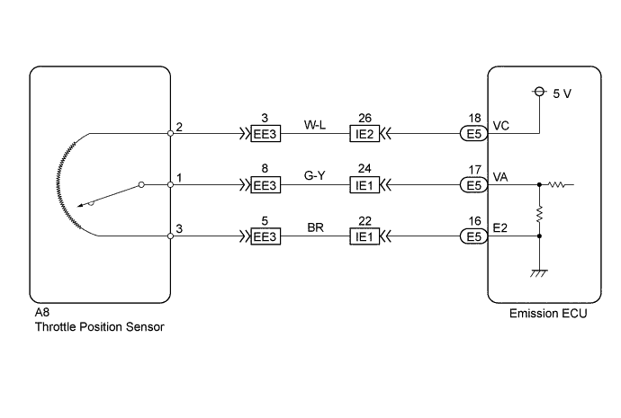
WIRING DIAGRAM
INSPECTION PROCEDURE
Tech Tips
If DTC "22" (water temperature sensor circuit), "31" (vacuum sensor circuit) and "41" (throttle position sensor circuit) are output simultaneously, E2 (sensor ground) may be open.
PROCEDURE
-
CHECK EMISSION CONTROL ECU
-
Turn the ignition switch ON
-
Apply vacuum to the throttle opener.
-
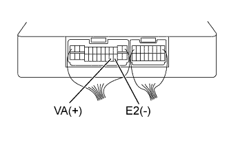
Measure the voltage between terminals VA and E2 of the emission ECU when the adjusting lever is turning to the maximum speed side gradually from idle speed side.
VOLTAGE Adjusting Lever Voltage Idle speed side 3.2-4.9V Maximum speed side 0.2-1.6V Tech Tips
The voltage should increase steadily in proportion to the adjusting valve opening angle.
OK 
CHECK FOR PROBLEM SYMPTOMS TABLE Click here
NG 
-
-
CHECK THROTTLE POSITION SENSOR
-
Disconnect the throttle position sensor connector.
-
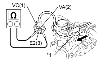
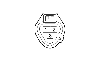
Text in Illustration *1 Adjusting Lever Measure the resistance between terminals 1 and 2, and 2 and 3 of the throttle position sensor connector when the adjusting lever is turning to the maximum speed side, gradually from the idle speed side.
RESISTANCE Terminal Throttle valve Resistance 2 - 3 - 2.1 - 3.16 kΩ 1 - 3 Idle speed side 1.3 - 3.16 kΩ 1 - 3 Maximum speed side 0 - 1.01 kΩ Tech Tips
The resistance between terminals 2 and 3 should increase gradually in accordance with the adjusting valve angle.
NG
REPLACE THROTTLE POSITION SENSOR
OK
-
-
CHECK WIRE HARNESS OR CONNECTOR (EMISSION ECU-THROTTLE POSITION SENSOR)
-
Disconnect the throttle position sensor connector.
-
Disconnect the emission ECU connector.
-
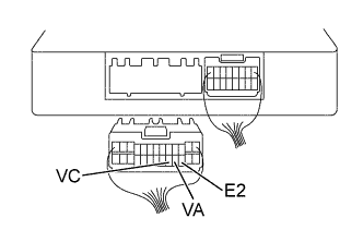
Check the continuity between terminals 2 of the throttle position sensor harness connector and VC of the ECU connector Click here.
RESISTANCE 1 Ωor less -
Check for short between terminals 2 of the throttle position sensor harness connector and VC of the ECU connector Click here.
RESISTANCE 1 MΩ or more -
Check the continuity between terminals 1 of the throttle position sensor harness connector and VA of the ECU connector Click here.
RESISTANCE 1 Ω or less -
Check for short between terminals 1 of the throttle position sensor harness connector and VA of the ECU connector Click here.
RESISTANCE 1 MΩ or more -
Check the continuity between terminals 3 of the throttle position sensor harness connector and E2 of the ECU connector Click here.
RESISTANCE 1 Ω or less -
Check for short between terminals 3 of the throttle position sensor harness connector and E2 of the ECU connector Click here.
RESISTANCE 1 MΩ or more
NG
REPAIR OR REPLACE WIRE HARNESS OR CONNECTOR
OK 
CHECK AND REPLACE EMISSION CONTROL ECU Click here
-