EMISSION CONTROL SYSTEM, Diagnostic DTC:31

| DTC Code | DTC Name |
|---|---|
| 31 | Vacuum Sensor Circuit |
DESCRIPTION
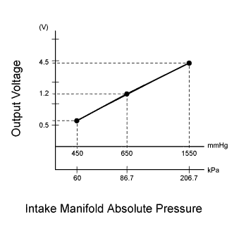
By a built-in sensor unit, the vacuum sensor detects the intake manifold pressure as a voltage. The emission ECU then determines the basic injection duration and basic ignition advance angle based on this voltage.
Since the vacuum sensor does not use the atmospheric pressure as a criterion but senses the absolute pressure inside the intake manifold (the pressure in proportion to the preset absolute vacuum 0), it is not influenced by fluctuations in the atmospheric pressure due to high altitude and other factors. This causes it to control the airfuel ratio at the proper level under any conditions.
| DTC No. | DTC Detecting Condition | Trouble Area |
|---|---|---|
| 31 | Open or short in vacuum sensor circuit for 0.2 sec. or more |
|
If the ECU detects DTC "31", it operates the fail safe function, keeping the ignition timing and fuel injection volume constant and making it possible to drive the vehicle.
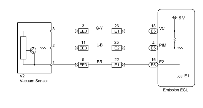
WIRING DIAGRAM
INSPECTION PROCEDURE
Tech Tips
If DTC "22" (water temperature sensor circuit), "31" (vacuum sensor circuit) and "41" (throttle position sensor circuit) are output simultaneously, E2 (sensor ground) may be open.
PROCEDURE
-
CHECK EMISSION CONTROL ECU
-
Turn the ignition switch ON.
-

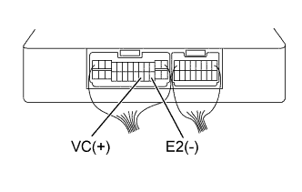
Measure the voltage between terminals VC and E2 of the emission ECU E1 connector.
VOLTAGE 4.5 - 5.5 V
NG 
CHECK AND REPLACE EMISSION CONTROL ECU Click here
OK 
-
-
CHECK EMISSION CONTROL ECU
-
Turn the ignition switch ON.
-
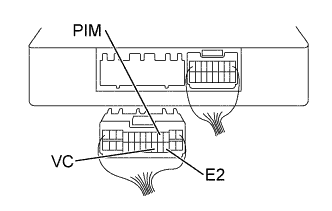
Measure the voltage between terminals PIM and E2 of the emission ECU connector.
VOLTAGE 3.3 - 3.9 V
OK
CHECK AND REPLACE EMISSION CONTROL ECU Click here
NG
-
-
CHECK WIRE HARNESS OR CONNECTOR (EMISSION ECU-VACUUM SENSOR)
-
Disconnect the vacuum sensor connector.
-
Disconnect the emission ECU connector.
-
Check the continuity between terminals 3 of the vacuum sensor harness connector and VC of the ECU connector Click here.
RESISTANCE 1 Ω or less -
Check for short between terminals 3 of the vacuum sensor harness connector and VC of the ECU connector Click here.
RESISTANCE 1 MΩ or more -
Check the continuity between terminals 2 of the vacuum sensor harness connector and PIM of the ECU connector Click here.
RESISTANCE 1 Ω or less -
Check for short between terminals 2 of the vacuum sensor harness connector and PIM of the ECU connector Click here.
RESISTANCE 1 MΩ or more -
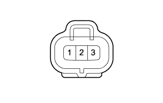
Check the continuity between terminals 1 of the vacuum sensor harness connector and E2 of the ECU connector Click here.
RESISTANCE 1 Ω or less -
Check for short between terminals 1 of the vacuum sensor harness connector and E2 of the ECU connector Click here.
RESISTANCE 1 MΩ or more
NG
REPAIR OR REPLACE WIRE HARNESS AND CONNECTOR
OK 
REPLACE VACUUM SENSOR
-