EMISSION CONTROL SYSTEM DIAGNOSIS SYSTEM

-
DIAGNOSIS SYSTEM
-
Description
The emission ECU contains a built-in self-diagnosis system which detects troubles via the engine signal network and then flashes the glow indicator light on the combination meter.
By analyzing various signals as shown in the later table Click here the emission ECU detects system malfunctions which are related to the various operating parameter sensors.
The DTC (diagnostic trouble code) can be read by the number of blinks of the glow indicator light when terminals TE1 and E1 on the check connector are connected. When 2 or more codes are indicated, the smallest numbered code will appear first.
-
-
DIAGNOSIS INSPECTION
-
Check the glow indicator light.
-
Text in Illustration *a Glow Indicator Light The glow indicator light will light up when the ignition switch is turned ON and the engine is not running.
Tech Tips
If the glow indicator light does not light up, proceed to troubleshooting of the combination meter.
-
When the engine is started, the glow indicator light should go off.
If the light remains on, the diagnosis system has detected a malfunction or abnormality in the system.
-
-
Check DTC.
-
Turn the ignition switch ON.
-
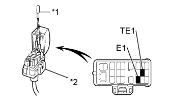
Text in Illustration *1 SST *2 Check Connector Using SST, connect terminals between TE1 and E1 of the check connector.
- SST
- 09843-18020
-
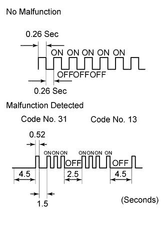
Read the DTC from glow indicator light.
As an example, the blinking patterns for codes; normal, 13 and 31 are shown in the illustration.
Tech Tips
If a DTC is not output, check the TE1 terminal circuit Click here.
-
Check the details of the malfunction using the DTC chart on page Click here.
-
After completing the check, disconnect the SST from terminals TE1 and E1, and turn off the display.
Tech Tips
If the event of 2 or more malfunction codes are output, indication will begin from the smallest numbered code and continue in order to the largest.
-
-