FUEL INJECTION PUMP REASSEMBLY

Note
w/ HAC:
When re-using the governor cover assembly, to prevent oil spilling out from the bushing of the governor cover when doing steps 21 and 32, removal and installation should be done without tilting it by 45°or more from the horizontal.
-
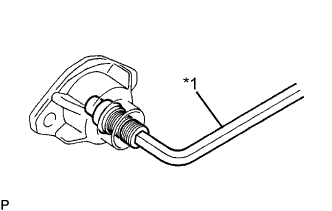
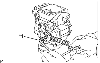
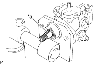
INSTALL OIL SEAL
-
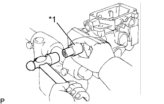
Text in Illustration *1 22 mm Socket Wrench Apply MP grease to the lip of a new oil seal.
-
Using a 22 mm socket wrench, tap in the oil seal until its surface is flush with the pump body.
-
-
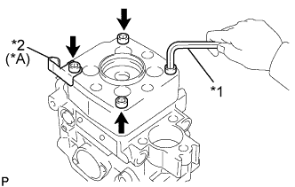
INSTALL FUEL INLET HOLLOW SCREW
-
Install a new gasket and the hollow screw.
- Torque:
- 36.8 N*m { 375 kgf*cm, 27 ft.*lbf }
-
-
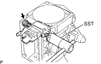
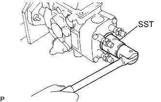
INSTALL REGULATOR VALVE SUB-ASSEMBLY
-
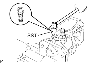
Install the 2 O-rings to the regulator valve.
-
Using SST, install the regulator valve.
- SST
- 09260-54012 ( 09262-54020 )
- Torque:
- 8.85 N*m { 90 kgf*cm, 78 in.*lbf }
-
-
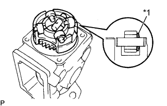
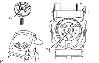
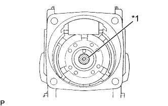
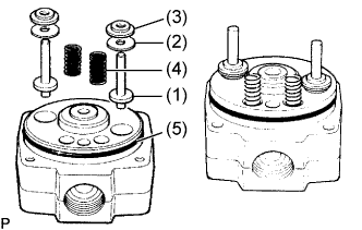
INSTALL FUEL FEED PUMP SUB-ASSEMBLY
-
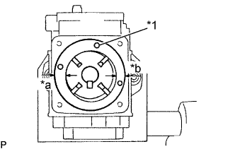
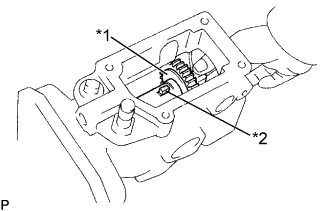
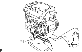
Text in Illustration *1 Fuel Outlet Hole *a Wide *b Narrow Install the liner, rotor and 4 blades.
-
Check that the liner and blades are facing in the correct direction, as shown.
-
Check that the blades move smoothly.
-
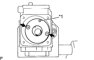
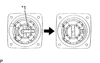
Text in Illustration *1 Fuel Outlet Hole Align the fuel outlet holes of the cover and liner.
-
Install the pump cover with the 2 screws.
- Torque:
- 2.95 N*m { 30 kgf*cm, 26 in.*lbf }
-
Check that the rotor moves smoothly.
-
-
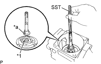
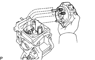
INSTALL DRIVE SHAFT SUB-ASSEMBLY
-
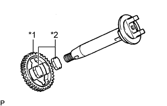
Text in Illustration *1 Drive Gear *2 Joint Rubber Install the drive gear on the drive shaft assembly as shown.
-
Install 2 new joint rubbers into the drive gear.
-
Position the key groove of the feel pump rotor upward.
-
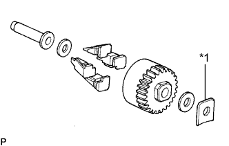
Text in Illustration *1 Drive Shaft Washer *2 Set key Install the set key and drive shaft washer on the drive shaft and insert the drive shaft.
-
-
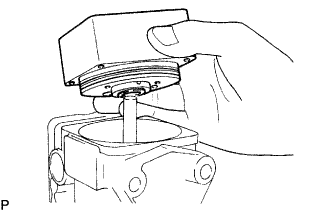
INSTALL TIMER PISTON ASSEMBLY
-
Apply grease to the timer piston.
-
Install the sub-piston into the timer piston.
-
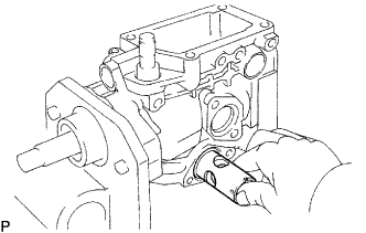
Insert the timer piston into the pump housing.
-
-
INSTALL ROLLER RING SUB-ASSEMBLY
-
Turn the drive shaft by approximately 90° clockwise or counterclockwise.
-
Text in Illustration *1 Washer Install the slide pin, 4 rollers and washers on the roller ring.
-
Check that the roller is facing the flat surface of the washer.
-
Install the roller ring into the pump housing.
-
Text in Illustration *1 Slide Pin Carefully install the slide pin into the sub-piston.
-
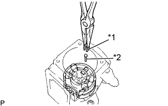
Text in Illustration *1 Clip *2 Stopper Pin Install the stopper pin and clip.
-
-
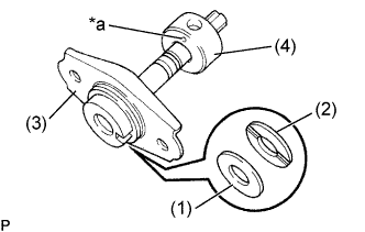
INSTALL TIMER SPRING
-
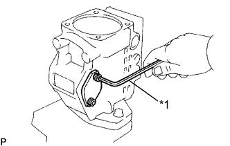
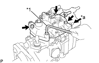
Text in Illustration *1 5 mm Hexagon Wrench Using a 5 mm hexagon wrench, install a new O-ring and the RH timer cover with the 2 bolts.
- Torque:
- 8.35 N*m { 85 kgf*cm, 74 in.*lbf }
-
Install a new O-ring to the timer adjusting screw.
-
Using a 5 mm hexagon wrench, install the timer adjusting screw to the LH timer cover and temporarily install the nut.
Text in Illustration *1 5 mm Hexagon Wrench -
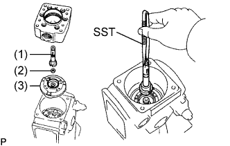
Install the timer inner spring (1), timer outer spring (2), spring washer (3), a new gasket (4), the LH timer cover, timer adjusting screw and nut assembly.
-
Text in Illustration *1 5 mm Hexagon Wrench Using a 5mm hexagon wrench, install the 2 LH timer cover bolts.
- Torque:
- 8.35 N*m { 85 kgf*cm, 74 in.*lbf }
-
-
ADJUST TIMER ADJUSTING SCREW
-
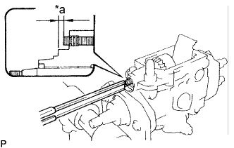
Text in Illustration *a Protrusion Using vernier calipers, measure the protrusion of the adjusting screw from the timer cover.
Protrusion 5.0 to 6.0 mm (0.197 to 0.236 in.) -
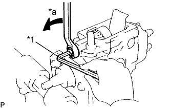
Text in Illustration *1 5 mm Hexagon Wrench Using a 5 mm hexagon wrench, adjust the protrusion of the adjusting screw from the timer cover.
- Torque:
- 14.2 N*m { 145 kgf*cm, 10 ft.*lbf }
-
-
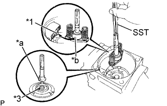
ADJUST PLUNGER SPRING SHIM
-
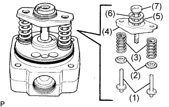
Install the 2 plunger spring guides (1), 2 upper spring seats (2), 2 plunger springs (3), lower spring seat (4), upper plunger plate (5), lower plunger plate (6) and pump plunger to the distributive head.
Tech Tips
Do not assemble the plunger spring shims this time.
-
Using vernier calipers, measure clearance A indicated in the illustration.
-
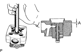
Determine the plunger spring shim size by using these formula and chart.
New plunger spring shim thickness = 6.3 - A
A ..... Measured plunger position.
Plunger spring shim selection chart Measured clearance Shim thickness More than 5.3 mm (0.209 in.) 0.5 mm (0.020 in.) 5.0 to 5.2 mm (0.196 to 0.205 in.) 0.8 mm (0.031 in.) 4.8 to 4.9 mm (0.189 to 0.193 in.) 1.0 mm (0.039 in.) 4.6 to 4.7 mm (0.181 to 0.185 in.) 1.2 mm (0.047 in.) 4.0 to 4.2 mm (0.169 to 0.177 in.) 1.5 mm (0.059 in.) 4.0 to 4.2 mm (0.157 to 0.165 in.) 1.8 mm (0.071 in.) Less than 3.9 mm (0.154 in.) 2.0 mm (0.079 in.) Tech Tips
-
For a measurement between listed sizes, use the next larger size. For example, if the thickness is 1.1 mm(0.043 in.) by calculation, use a 1.2 mm (0.047 in.) shim.
-
Select 2 shims which have the same thickness.
-
-
-
INSTALL FACE CAMPLATE SUB-ASSEMBLY
-
Text in Illustration *1 Face Camplate *2 Coupling *3 Spacer Install the spacers, coupling and face camplate.
-
Text in Illustration *a Key Groove Install the spacers and coupling.
-
Turn the key groove of the drive shaft upward.
-
Text in Illustration *1 Pin Install the coupling spring and camplate with the camplate pin facing the governor cover side.
-
-
ADJUST PLUNGER SHIM
-
Text in Illustration *1 Pin *a Pin Groove Install the face camplate.
Tech Tips
Do not install the coupling spring.
-
Clean the plunger adjusting shim and contacting surface area.
-
Align the pin groove of the pump plunger with the face camplate pin.
-
Using SST, install the used plunger adjusting shim and pump plunger.
- SST
- 09260-54012 ( 09269-54030 )
-
Install the distributive head with the 4 bolts.
- Torque:
- 11.75 N*m { 120 kgf*cm, 9 ft.*lbf }
Note
Be careful not to damage the pump plunger.
-
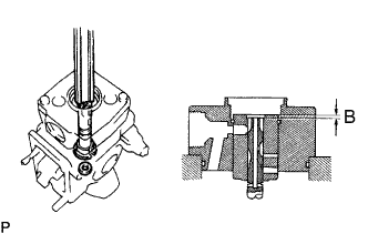
Using vernier calipers, measure dimension B indicated in the illustration.
-
Determine the plunger adjusting shim size by using these formula and chart:
New adjusting shim thickness = T + (B - 3.3)
T ... Thickness of used shim
B ... Measured plunger position
Plunger adjusting shim selection chart 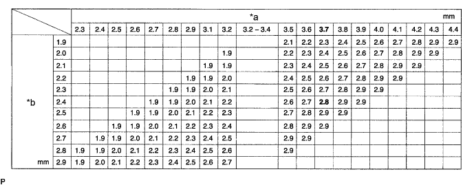
Text in Illustration *a Measured clearance *b Installed shim Plunger adjusting shim thickness: 1.9 mm (0.075 in.) 2.5 mm (0.098 in.) 2.0 mm (0.079 in.) 2.6 mm (0.102 in.) 2.1 mm (0.083 in.) 2.7 mm (0.106 in.) 2.2 mm (0.087 in.) 2.8 mm (0.110 in.) 2.3 mm (0.091 in.) 2.9 mm (0.114 in.) 2.4 mm (0.094 in.) EXAMPLE The 2.4 mm (0.094 in.) shim is installed and measured clearance is 3.7 mm (0.146 in.). Replace the 2.4 mm (0.094 in.) shim with a 2.8 mm (0.110 in.) shim. -
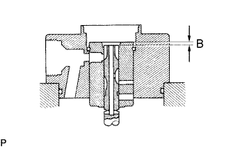
Install a new plunger adjusting shim, and recheck dimension B.
Dimension B: 3.2 to 3.4 mm (0.126 to 0.134 in.) -
Remove the distributive head.
-
Using SST, remove the pump plunger (1), plunger adjusting shim (2) and face camplate (3).
- SST
- 09260-54012 ( 09269-54030 )
-
-
INSTALL GOVERNOR LINK
-
Using SST, install the governor link with 2 new gaskets and the 2 support bolts.
- Torque:
- 13.75 N*m { 140 kgf*cm, 10 ft.*lbf }
- SST
- 09260-54012 ( 09269-54040 )
-
Check that the governor link moves smoothly.
-
-
INSTALL PUMP PLUNGER
-
Text in Illustration *1 Shim Place the selected new plunger adjusting shim on the center of the camplate.
Note
Do not apply grease to the shim.
-
Text in Illustration *a Hole Install the lower plunger plate (1), upper plunger plate (2), lower spring seat (3) and spill ring (4) to the pump plunger.
Tech Tips
The spill ring with the hole faces the lower spring seat.
-
Text in Illustration *1 Ball Pin *2 Pin *a Pin Groove *b Pin Hole Align the pin groove of the plunger with the pin of the face camplate.
-
Align the ball pin of the governor link with the pin hole of the spill ring.
-
Using SST, install the pump plunger and 2 plunger springs.
- SST
- 09260-54012 ( 09269-54030 )
-
-
INSTALL DISTRIBUTIVE PUMP HEAD SUB-ASSEMBLY
-
Apply grease to the 2 plunger spring guides (1), 2 new selected plunger spring shims (2), 2 upper spring seats (3), 2 lever support springs (4) and a new O-ring (5), and install them to the distributive head.
-
Install the distributive head.
Note
Be careful not to damage the pump plunger.
-
Text in Illustration *A w/ TCV *1 5 mm Hexagon Wrench *2 Clamp Using a 5 mm hexagon wrench, install the lead clamp (w/ TCV) and 4 bolts. Uniformly tighten the bolts in several passes.
- Torque:
- 11.75 N*m { 120 kgf*cm, 9 ft.*lbf }
Tech Tips
Use the bolt which length is 45 mm (1.77 in.).
-
-
INSTALL INJECTION PUMP DELIVERY VALVE SUB-ASSEMBLY
-
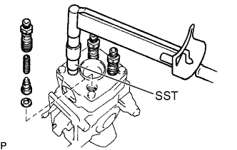
Install new gaskets and the valves into the distributive head.
-
Install the springs into the delivery valve holders.
-
Using SST, install the delivery valve holders.
- SST
- 09260-54012 ( 09262-54010 )
- Torque:
- 58.85 N*m { 600 kgf*cm, 43 ft.*lbf }
-
-
INSTALL DISTRIBUTIVE HEAD PLUG
-
Install a new O-ring to the head plug.
-
Using SST, install the head plug.
- SST
- 09260-54012 ( 09262-54010 )
- Torque:
- 68.65 N*m { 700 kgf*cm, 51 ft.*lbf }
-
-
INSTALL GOVERNOR SHAFT AND FLYWEIGHT HOLDER
-
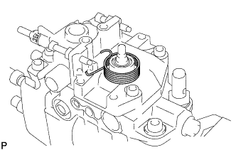
Install the 4 flyweights (1), No. 2 flyweight washer (2) and governor sleeve (3) to the flyweight holder:
Tech Tips
Replace the 4 flyweights as a set.
-
Text in Illustration *1 5 mm Hexagon Wrench Install a new O-ring to the governor shaft.
-
Place the flyweight holder assembly (1) in position, and install the governor gear adjusting washer (2) and No.1 flyweight washer (3) between the flyweight holder and pump housing.
-
Install the governor shaft through the governor gear adjusting washer, No.1 flyweight washer and flyweight holder assembly.
-
Using a 5 mm hexagon wrench, turn the governor shaft counterclockwise.
Tech Tips
The governor shaft has LH threads.
-
Check the flyweight holder thrust clearance.
-
Using a feeler gauge, measure the thrust clearance between the housing pin and flyweight holder.
Thrust clearance 0.15 to 0.35 mm (0.059 to 0.0138 in.) If the thrust clearance is not as specified, adjust it with a governor gear adjusting washer.
Text in Illustration *1 Adjusting Washer Governor gear adjusting washer thickness: 1.05 mm (0.0413 in.) 1.65 mm (0.0650 in.) 1.25 mm (0.0492 in.) 1.85 mm (0.0728 in.) 1.45 mm (0.0571 in.) -
-
-
-
ADJUST PROTRUSION OF GOVERNOR SHAFT
-
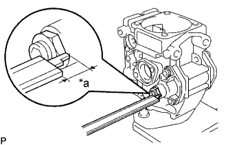
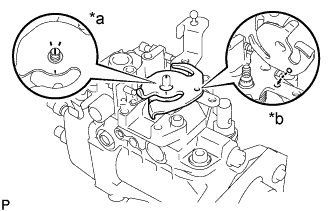
Text in Illustration *a 0.5 to 2.0 mm Using vernier calipers, measure the protrusion of the governor shaft.
Protrusion 0.5 to 2.0 mm (0.020 to 0.079 in.) If the protrusion is not as specified, adjust it by turning the governor shaft.
Tech Tips
The governor cover shaft has LH threads.
-
Text in Illustration *1 5 mm Hexagon Wrench *a Turn Install and tighten the nut while holding the governor shaft with a 5 mm hexagon wrench.
-
-
INSTALL HIGH ALTITUDE COMPENSATOR (w/ HAC:)
-
Text in Illustration *A w/ HAC Install the control lever.
-
Insert the connecting pin into the governor cover.
-
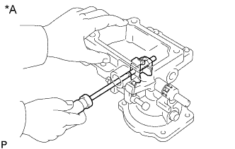
Text in Illustration *A w/ HAC Using a small screwdriver, install the control lever with the support pin.
-
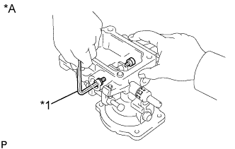
Text in Illustration *A w/ HAC *1 4 mm Hexagon Wrench Using a 4 mm hexagon wrench, install 2 new gaskets and the 2 bolts.
- Torque:
- 6.85 N*m { 70 kgf*cm, 61 in.*lbf }
-
-
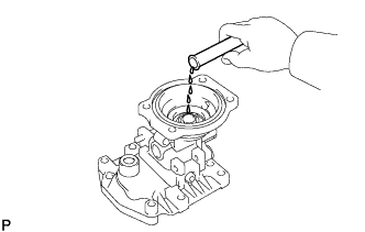
Install the pneumatic bellows.
-
Insert 1.5 to 2.5 cc (0.09 to 0.15 cu in.) of engine oil into the bushing hole.
-
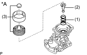
Text in Illustration *A w/ HAC Install the pneumatic bellows spring (1), push rod (2), the pneumatic bellows and 2 rubber caps (3).
-
Text in Illustration *A w/ HAC *1 5 mm Hexagon Wrench Using a 5mm hexagon wrench, install a new gasket and the pneumatic bellows cover with the 4 bolts.
- Torque:
- 7.35 N*m { 75 kgf*cm, 65 in.*lbf }
-
-
Text in Illustration *A w/ HAC *1 Bolt *2 New Gasket *3 Lever Control Spring *4 Rubber Cap 
Arrow Mark Install the rubber cap.
Install the rubber cap with the arrow mark facing downward.
-
Install the lever control spring.
Install the lever control spring with a new gasket and the bolt.
- Torque:
- 12.75 N*m { 125 kgf*cm, 9 ft.*lbf }
-
-
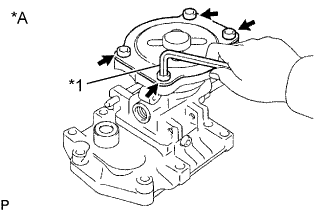
INSTALL GOVERNOR COVER SUB-ASSEMBLY
-
Text in Illustration *A M/T *1 Speed Control Spring *2 Damper Spring *3 Spring Seat *a Attach Install the plate washer and a new O-ring to the adjusting lever shaft.
-
M/T:
Install the damper spring, spring seat, speed control spring and adjusting lever shaft to the governor link.
-
Text in Illustration *A A/T *a Connect *b Attach A/T:
Connect the adjusting lever shaft to the governor link.
-
Install the adjusting lever shaft to the governor cover.
-
Attach the full load set screw to the governor link.
-
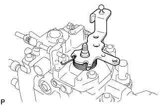
Text in Illustration *1 5 mm Hexagon Wrench *a Slide Slide the governor cover forward.
-
Using a 5 mm hexagon wrench, install the governor cover with the 4 bolts. Uniformly tighten the bolts in several passes.
- Torque:
- 8.35 N*m { 85 kgf*cm, 74 in.*lbf }
Tech Tips
Use the bolt which length is 35 mm (1.38 in.).
-
w/ HAC:
Install the idle speed adjusting screw.
-
-
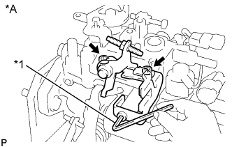
INSTALL ADJUSTING LEVER SUB-ASSEMBLY
-
Place the return spring on the governor cover as shown in the illustration.
-
Hook the return spring to the No.1 adjusting lever.
-
Attach the No.1 adjusting lever to the idle speed adjusting screw end.
-
Text in Illustration *a Align *b Attach Align the lines of the adjusting shaft and No.2 adjusting lever.
-
Attach the protrusion of the No.2 adjusting lever to the hole of the No.1 adjusting lever.
-
Place the No.2 adjusting lever on the No.1 adjusting lever.
-
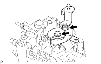
Install the 2 adjusting levers with the nut and bolt.
- Torque:
- 8.35 N*m { 85 kgf*cm, 74 in.*lbf, for nut }
- 6.05 N*m { 62 kgf*cm, 54 in.*lbf, for bolt }
-
-
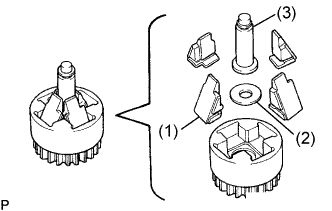
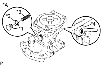
INSTALL FUEL CUT SOLENOID ASSEMBLY
-
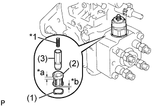
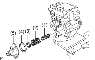
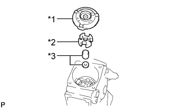
Text in Illustration *1 Spring *a Wide *b Narrow Install the wave washer (1), strainer (2), valve (3) and spring.
Note
Be careful of the strainer (2) installation direction.
-
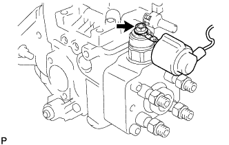
Install a new O-ring to the fuel cut solenoid.
-
Install the fuel cut solenoid.
- Torque:
- 22.1 N*m { 225 kgf*cm, ft.*lbf }
-
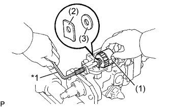
Install the lead wire to the fuel cut solenoid with the nut.
- Torque:
- 1.7 N*m { 17.5 kgf*cm, 15 in.*lbf }
-
Install the dust cover to the fuel cut solenoid.
-
-
INSTALL CONNECTOR BRACKET
-
Text in Illustration *A w/o TCV *1 6 mm Hexagon Wrench Using a 6 mm hexagon wrench, install the connector bracket with the bolt.
- Torque:
- 20.1 N*m { 205 kgf*cm, 15 ft.*lbf }
-
-
INSTALL ENGINE SPEED SENSOR
-
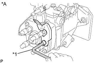
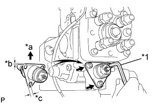
Text in Illustration *A w/ TCV Install a new O-ring and the engine speed sensor.
- Torque:
- 22.1 N*m { 216 kgf*cm, 16 ft.*lbf }
-
w/TCV:
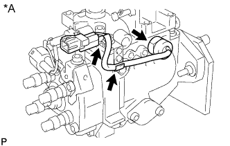
Install the lead wire and connector to lead clamp on the governor cover.
-
Install the lead wire and connector to the lead clamp on the governor cover.
-
Connect the lead wire for the fuel cut solenoid to the connector.
-
Install the connector to the connector bracket on the distributive head.
-
Install a new O-ring and the engine speed sensor.
- Torque:
- 22.1 N*m { 216 kgf*cm, 16 ft.*lbf }
-
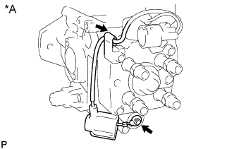
Text in Illustration *A w/o TCV w/o TCV:
Connect the lead wire for the fuel cut solenoid to the connector.
-
Install the connector to connector bracket on the distributive head.
-
Install the lead wire to the lead clamp on the governor cover.
-
-
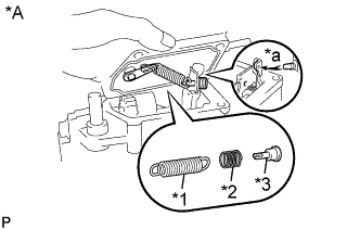
INSTALL TIMING CONTROL VALVE (w/ TCV)
-
Text in Illustration *1 5 mm Hexagon Wrench *a Upward *b Narrow *c Wide Install 2 new O-rings and the timing control valve.
-
Using a 5 mm hexagon wrench, install the wave washer, strainer and timing control valve with the 3 bolts.
- Torque:
- 8.35 N*m { 85 kgf*cm, 74 in.*lbf }
Note
Be careful of the installation direction.
-
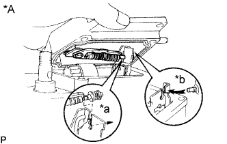
Text in Illustration *A w/ TCV Install the lead wire to the timing control valve with the nut.
- Torque:
- 1.7 N*m { 17.5 kgf*cm, 15 in.*lbf }
-
Install the dust cover to the timing control valve.
-
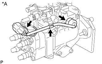
Install the lead wire to the lead clamp on the distributive head.
-
-
INSTALL TIMER COVER SUB-ASSEMBLY (THERMO WAX) (w/ ACSD)
-
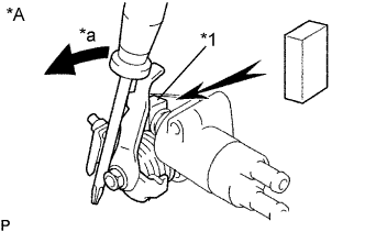
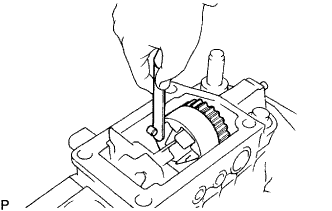
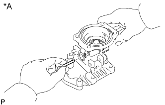
Text in Illustration *A w/ ACSD *1 Metal Plate *a Turn Using a screwdriver, turn the cold starting lever by approximately 20°counterclockwise.
-
Put a metal plate (thickness of 8.5 to 10.0 mm (0.335 to 0.394 in.)) between the cold starting lever and thermo wax plunger.
-
Text in Illustration *A w/ ACSD *1 5 mm Hexagon Wrench Install a new gasket to the pump body.
-
Using a 5 mm hexagon wrench, install the thermo wax with the 2 bolts.
- Torque:
- 6.85 N*m { 67 kgf*cm, 58 in.*lbf }
-
Remove the metal plate.
-
-
PERFORM AIR TIGHT TEST
-
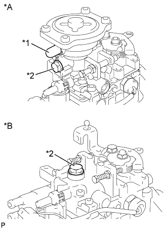
Text in Illustration *A w/ HAC *B w/o HAC *1 Plug *2 Bolt Plug each port with a bolt and plug.
-
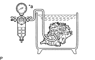
Text in Illustration *a 49 to 490 kPa Connect an air hose to the fuel inlet pipe and place the injection pump in diesel fuel.
-
Apply 49 kPa (0.5 kgf*cm2, 7psi) of pressure and confirm that there are no leaks.
-
Check that there are no leaks with 490 kPa (5.0 kgf*cm2, 71psi) of pressure applied.
-
Remove the bolt and plug from the overflow port and idle-up actuator.
-
-
INSTALL IDLE-UP SUB-ASSEMBLY (w/ ACSD)
-
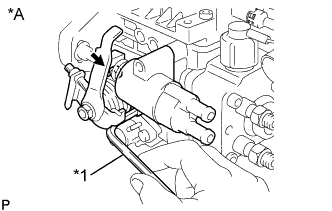
Text in Illustration *A w/ ACSD *1 5 mm Hexagon Wrench Using a 5 mm hexagon wrench, install the idle-up sub-assembly with the 3 bolts. Alternately tighten the bolts in several passes.
- Torque:
- 8.35 N*m { 85 kgf*cm, 74 in.*lbf }
-
-
REMOVE INJECTION PUMP FROM SST (STAND)
- SST
- 09241-76022
- 09245-54010
-
INSTALL SET KEY OF INJECTION PUMP DRIVE PULLEY ON DRIVE SHAFT