FUEL INJECTION PUMP ADJUSTMENT

-
PRE-TEST CHECK AND PREPARATION
-
The specifications for test nozzle and nozzle holders are as follows.
Test nozzle DN12SD12 (DENSO) Test nozzle opening pressure 14220 to 15200 kPa (145 to 155 kgf*cm2, 2062 to 2205 psi) -
Check the accuracy of the tachometer.
Allowable error 610 to 790 rpm -
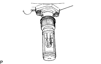
Install the angle gauge stand.
-
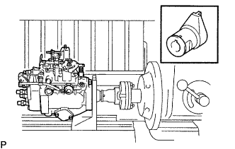
Mount the injection pump body on the pump tester.
Tech Tips
Place a mark on the key groove portion of the coupling.
-
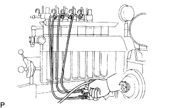
Install an injection pipe with these specifications.
Outer diameter 6.0 mm (0.236 in.) Inner diameter 2.0 mm (0.079 in.) Length 840 mm (33.07 in.) Minimum bending radius 25 mm (0.98 in.) or more -
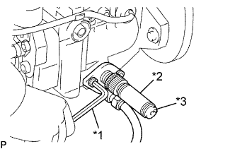
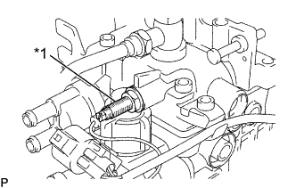
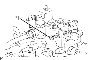
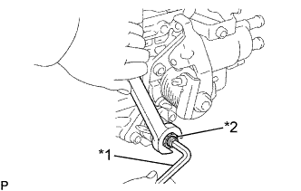
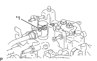
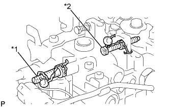
Remove the fuel inlet hollow screw.
-
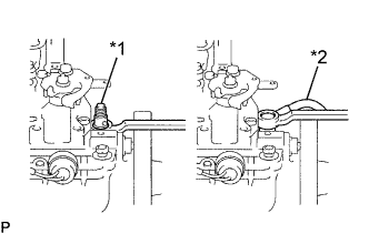
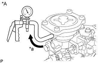
Text in Illustration *1 Fuel Inlet Hollow Screw *2 Fuel Inlet Pipe Connect the fuel inlet pipe with an adapter.
- Torque:
- 26.55 N*m { 260 kgf*cm, 19 ft.*lbf }
-
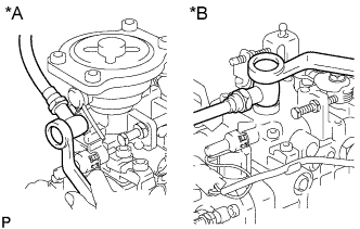
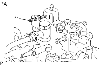
Text in Illustration *A w/ HAC *B w/o HAC Install an overflow hose with the 2 gaskets and an overflow screw.
- Torque:
- 26.55 N*m { 260 kgf*cm, 19 ft.*lbf }
Tech Tips
Always use the overflow screw installed on the pump for adjustment.
-
Text in Illustration *1 5 mm Hexagon Wrench *2 Timer Measuring Device *3 Air Bleed Screw Using a 5 mm hexagon wrench, remove the 2 bolts and RH timer cover.
-
Install the inner pressure gauge with the timer measuring device.
Part No. 95095-10231, 95095-10480 (DENSO)
- Torque:
- 8.35 N*m { 85 kgf*cm, 74 in.*lbf }
Tech Tips
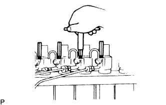
Bleed the air by the air bleed screw.
-
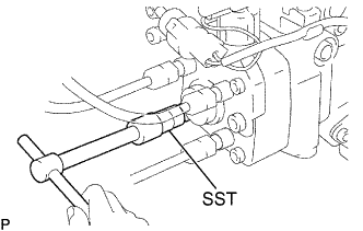
Connect SST (turbocharger pressure gauge) to the boost compensator.
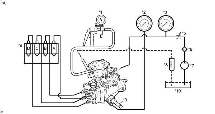
Text in Illustration *A w/ HAC - - *1 Vacuum Gauge *2 Inner Pressure Gauge *3 Fuel Pressure Gauge *4 Nozzle *5 Adjusting Valve *6 Fuel Filter *7 Fuel Feed Pump *8 Measuring Cylinder *9 Timer Measuring Device *10 Fuel Tank 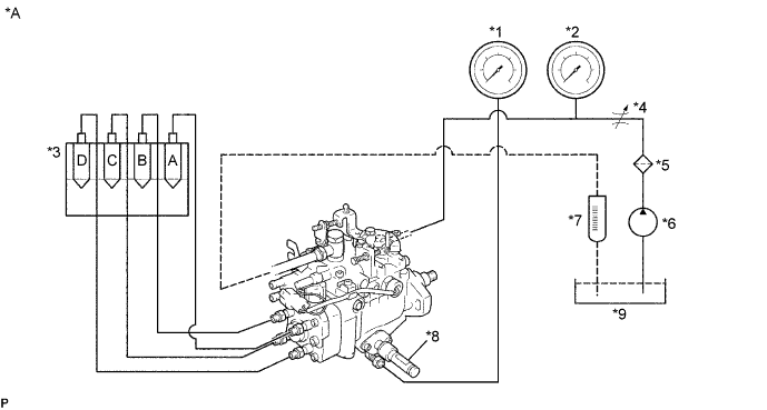
Text in Illustration *A w/o HAC - - *1 Inner Pressure Gauge *2 Fuel Pressure Gauge *3 Nozzle *4 Adjusting Valve *5 Fuel Filter *6 Fuel Feed Pump *7 Measuring Cylinder *8 Timer Measuring Device *9 Fuel Tank - - - SST
- 09992-00242
-
Apply about 6 bolts of DC power to the fuel cut solenoid.
Tech Tips
-
When applying voltage to the solenoid, position the battery as far away from the solenoid as possible so that spark does not occur.
-
When connecting the battery cable, connect the solenoid side first.
Tech Tips
Connect the battery through a 10 W bulb.
-
-
The pressure for feeding fuel to the injection pump should be 20 kPa (0.2 kgf*cm2, 2.8 psi). The fuel temperature for pump testing should be 40 to 45°C (104 to 113°F).
-
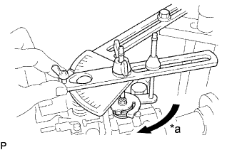
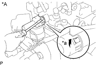
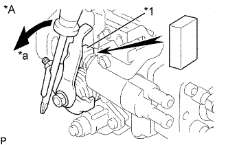
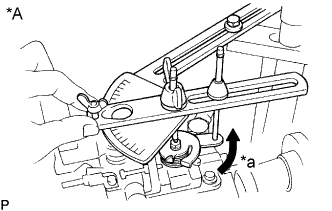
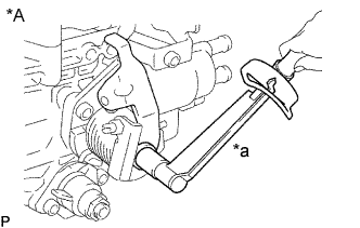
Text in Illustration *a Maximum Speed Side Install an angle gauge to the stand, and set it to the adjusting lever.
Part No. 95095-10360 (Stand w/ angle gauge)
-
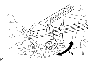
Secure the adjusting lever fully on the maximum speed side.
-
Check the installation direction of the camplate as follows:
-
Disconnect the injection pipe from the position by marked "C" on the distributive head.
-
Using SST, remove the delivery valve holder.
- SST
- 09260-54012 ( 09269-54020 )
-
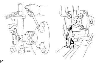
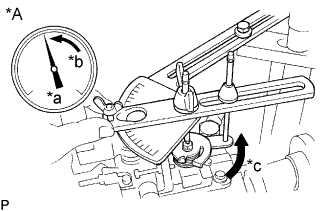
Check that fuel is flowing out when the mark is in the position shown in the illustration.
If not, it is improperly assembled.
-
Disassemble and change the camplate position by 180° in the opposite direction.
Tech Tips
At this time, disconnect the fuel cut solenoid wire harness.
-
Using SST, install the delivery valve holder.
- SST
- 09260-54012 ( 09269-54020 )
- Torque:
- 58.85 N*m { 600 kgf*cm, 43 ft.*lbf }
-
Connect the injection pipe.
-
-
Bleed the air from the injection pipes.
-
Race the injection pump for 5 minutes at 1,200 rpm.
Tech Tips
Replace the overflow screw to a hollow screw in this operation.
Note
Check that there is no fuel leakage or abnormal noise.
Tech Tips
-
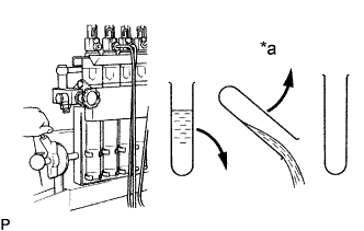
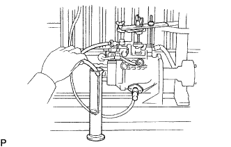
Measure the volume of each injection cylinder with a measuring cylinder.
Text in Illustration *a 30 Seconds -
Before measuring the injection volume, have the cylinder tilted for at least 30 seconds to discard all the fuel.
-
-
-
CHECK HIGH ALTITUDE COMPENSATOR FOR AIR TIGHTNESS
-
Text in Illustration *A w/ HAC *a Vacuum Apply 73 kPa (548 mmHg, 21.56 in.Hg) of vacuum to the high altitude compensator.
-
Measure how much time it takes for vacuum to drop to 72 kPa (540 mmHg, 21.26 in.Hg).
Vacuum drop 5 seconds or more
-
-
PRE-SET FULL LOAD INJECTION VOLUME
-
Set the adjusting lever to the maximum position.
-
w/ HAC:
Apply 101 kPa (760 mmHg, 29.83 in.Hg) of vacuum to the high altitude compensator.
-
Measure the injection volume.
Injection volume w/ ACSD (Part No. 22100-5D320) Pump rpm No. of measuring strokes Injection volume of each cylinder cc (cu in.) 1200 200 11.94 to 12.26 (0.73 to 0.75) w/o ACSD (Part No. 22100-5D110, 22100-5D230, 22100-5D250) Pump rpm No. of measuring strokes Injection volume of each cylinder cc (cu in.) 1600 200 12.42 to 12.74 (0.76 to 0.78) -
w/ Cap Seal Type:
-
Text in Illustration *A w/ Cap Seal Type *a Pry Disconnect the dust cover from the fuel cut solenoid.
-
Using a small screwdriver, pry the 4 claws.
-
Remove the cap seal.
-
-
w/ Wire Seal Type:
Cut off the wire seal.
-
Text in Illustration *1 Full Load Set Screw Adjust the injection volume by turning the full load set screw.
Tech Tips
The injection volume will increase about 3 cc (0.18 cu in.) with each 1/2 turns of the screw.
-
-
PRE-SET LOAD SENSING TIMER (w/o HAC)
-
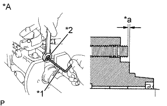
Text in Illustration *A w/o HAC *1 5 mm Hexagon Wrench *2 Governor Shaft *a 0.5 to 2.0mm Using a 5 mm hexagon wrench, adjust the protrusion of the governor shaft.
Protrusion (Part No. 22100-5D230, 22100-5D250) 0.5 to 2.0 mm (0.020 to 0.079 in.)
-
-
PRE-SET MAXIMUM SPEED
-
Set the adjusting lever to the maximum position.
-
w/ HAC:
Apply 101 kPa (760 mmHg, 29.83 in.Hg) of vacuum to the high altitude compensator.
-
Measure the injection volume.
Injection volume w/ ACSD (Part No. 22100-5D320) Pump rpm No. of measuring strokes Injection volume of each cylinder cc (cu in.) 2400 200 4.6 to 6.2 (0.28 to 0.38) w/o ACSD (Part No. 22100-5D110, 22100-5D230, 22100-5D250) Pump rpm No. of measuring strokes Injection volume of each cylinder cc (cu in.) 2300 200 7.46 to 9.46 (0.46 to 0.58) -
Text in Illustration *1 Maximum Speed Adjusting Screw Cut off the seal wire.
-
Adjust the injection volume with the maximum speed adjusting screw.
-
-
ADJUST PUMP INNER PRESSURE
-
Set the adjusting lever to the maximum position.
-
w/ HAC:
Apply 101 kPa (760 mmHg, 29.83 in.Hg) of vacuum to the high altitude compensator.
-
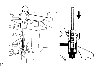
Measure the pump inner pressure at the rpm listed below.
Pump inner pressure Pump rpm Inner kPa (kgf*cm2, psi)
500 314 to 372 (3.2 to 3.8, 46 to 54) 2100 618 to 676 (6.3 to 6.9, 90 to 98) If the pressure is low, adjust the pressure by lightly tapping the regulator valve piston while watching the pressure gauge.
Text in Illustration 
Tap Tech Tips
If the pressure is too high or if the regulator valve was tapped in too far, the regulator valve must be replaced.
-
-
CHECK OVERFLOW VOLUME
-
Set the adjusting lever to the maximum position.
-
w/ HAC:
Apply 101 kPa (760 mmHg, 29.83 in.Hg) of vacuum to the high altitude compensator.
-
Measure the overflow volume at the rpm listed below.
Overflow volume Pump rpm Overflow volume cc/min. (cu in./min.) 2200 9.58 to 9.98 (0.59 to 0.61) Tech Tips
Always use the overflow screw installed on the pump for adjustment.
-
-
RELEASE COLD STARTING SYSTEM (w/ ACSD)
-
Text in Illustration *A w/ ACSD *1 Metal Plate *a Turn Using a screwdriver, turn the cold starting lever by approximately 20°counterclockwise.
-
Put a metal plate (thickness of 8.5 to 10.0 mm (0.335 to 0.394 in.)) between the cold starting lever and thermo wax plunger.
Tech Tips
Keep the cold starting system released until all measurements and adjustments are finished.
-
-
ADJUST TIMER
-
Set the timer measuring device at zero.
-
w/ HAC:
Apply 101 kPa (760 mmHg, 29.83 in.Hg) of vacuum to the high altitude compensator.
-
Measure the timer piston stroke at the rpm listed below.
Timer piston stroke w/ ACSD (w/ TCV) (Part No. 22100-5D320) Pump rpm Piston stroke mm (in.) 800 Full TCV ON 1.65 to 2.45 (0.0650 to 0.0965) 1200 Full TCV ON 3.41 to 4.21 (0.1343 to 0.1657) Full TCV OFF 1.48 to 2.46 (0.0583 to 0.0969) 1900 Full TCV ON 6.49 to 7.29 (0.2555 to 0.2870) 2200 Full TCV ON 7.06 to 7.54 (0.2780 to 0.2968) w/o ACSD (w/o TCV) (Part No. 22100-5D110, 22100-5D230, 22100-5D250) Pump rpm Piston stroke mm (in.) 850 0.23 to 1.03 (0.0091 to 0.0406) 1200 1.77 to 2.57 (0.0697 to 0.1012) 2000 5.30 to 6.10 (0.2087 to 0.2402) 2300 6.36 to 6.84 (0.2504 to 0.2693) Tech Tips
Check that the hysteresis is within 0.3 mm (0.012 in.).
-
Text in Illustration *1 5 mm Hexagon Wrench *2 Timer Adjusting Screw Using a 5 mm hexagon wrench, adjust it by turning the timer adjusting screw.
Tech Tips
Turn clockwise to reduce the stroke but turn counterclockwise to increase the stroke.
-
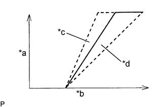
Text in Illustration *a Piston Stroke *b Pump rpm *c Long Spring *d Short Spring 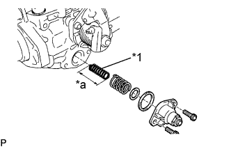
Text in Illustration *1 Timer Inner Spring *a Free Length Check the timer stroke for characteristic tendency.
If the tendency is not as specified, select and replace the timer (inner) spring.
Timer inner spring free length: 27.9 mm (1.098 in.) 33.5 mm (1.319 in.) 34.2 mm (1.346 in.) 32.5 mm (1.280 in.) 33.8 mm (1.331 in.) 34.7 mm (1.366 in.) Tech Tips
The timer stroke will increase with a long spring but decrease with a short spring.
-
-
ADJUST FULL LOAD INJECTION VOLUME
-
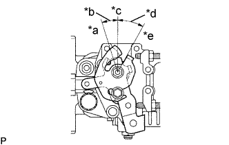
Text in Illustration *a Idle Speed Side *b Minus *c 0° *d Plus *e Maximum Speed Side The adjusting lever angle for the adjustment below should be as shown in the illustration.
Adjusting lever angle: A (Maximum speed side) B (Idle speed side) Plus 23 5 33 5° w/ ACSD Minus 12.5 to 22.5° w/o ACSD Minus 11.5 to 21.5° -
w/ HAC:
Apply 101 kPa (760 mmHg, 29.83 in.Hg) of vacuum to the high altitude compensator.
-
Measure the full load injection volume.
Injection volume w/ ACSD (Part No. 22100-5D320) Pump rpm No. of measuring strokes Injection volume of each cylinder cc (cu in.) 1200 200 11.94 to 12.46 (0.73 to 0.75) w/o ACSD (Part No. 22100-5D110, 22100-5D230, 22100-5D250) Pump rpm No. of measuring strokes Injection volume of each cylinder cc (cu in.) 1600 200 12.42 to 12.74 (0.76 to 0.78) -
Text in Illustration *1 Full Load Set Screw Adjust it by turning the full load set screw.
Tech Tips
The injection volume will increase about 3 cc (0.18 cu in.) with each 1/2 turns of the screw.
-
-
ADJUST MAXIMUM SPEED
-
w/ HAC:
Apply 101 kPa (760 mmHg, 29.83 in.Hg) of vacuum to the high altitude compensator.
-
Measure the injection volume at each pump rpm.
Injection volume w/ ACSD (Part No. 22100-5D320) Adjusting lever angle Pump rpm No. of measuring strokes Injection volume of each cylinder cc (cu in.) Remark 23.5 to 33.5° 2000 200 9.52 to 11.52 (0.58 to 0.70) - 2400 200 4.6 to 6.2 (0.28 to 0.38) Adjust 2800 200 1.3 (0.08) or less - w/o ACSD (Part No. 22100-5D110, 22100-5D230, 22100-5D250) Adjusting lever angle Pump rpm No. of measuring strokes Injection volume of each cylinder cc (cu in.) Remark 23.5 to 33.5° 2300 200 7.46 to 9.46 (0.46 to 0.58) - 2450 200 4.6 to 6.2 (0.28 to 0.38) Adjust 2700 200 1.3 (0.08) or less - -
Text in Illustration *1 Maximum Speed Adjusting Screw Adjust it by turning the maximum speed adjusting screw.
-
-
CHECK INJECTION VOLUME
-
Measure the injection volume at each pump rpm and HAC vacuum (w/ HAC).
Injection volume w/ ACSD (Part No. 22100-5D320) Adjusting lever angle Pump rpm No. of measuring strokes Injection volume of each cylinder cc (cu in.) Variation limit cc (cu in.) Remark Plus 23.5 to 33.5° 100 200 13.6 to 18.4 (0.83 to 1.12) 1.4 (0.09) Volume during starting 500 200 10.3 to 11.3 (0.63 to 0.69) 0.5 (0.03) - 1200 200 11.94 to 12.36 (0.73 to 0.75) 0.4 (0.02) Basic full load injection volume 1800 200 11.38 to 12.28 (0.69 to 0.75) 0.5 (0.03) - w/o ACSD (w/o HAC) (Part No. 22100-5D230) Adjusting lever angle Pump rpm No. of measuring strokes Injection volume of each cylinder cc (cu in.) Variation limit cc (cu in.) Remark Plus 23.5 to 33.5° 100 200 13.6 to 18.4 (0.83 to 1.12) 1.4 (0.09) Volume during starting 500 200 10.3 to 11.3 (0.63 to 0.69) 0.5 (0.03) - 1200 200 11.94 to 12.36 (0.73 to 0.75) 0.4 (0.02) Basic full load injection volume 1900 200 11.38 to 12.28 (0.69 to 0.75) 0.5 (0.03) - w/o ACSD (w/ HAC) (Part No. 22100-5D110, 22100-5D250) Adjusting lever angle Pump rpm HAC vacuum kPa (mmHg, in.Hg) No. of measuring strokes Injection volume of each cylinder cc (cu in.) Variation limit cc (cu in.) Remark Plus 23.5 to 33.5° 100 101 (760, 29.83) 200 13.6 to 18.4
(0.83 to 1.12)
(0.62 to 0.70)
1.4 (0.09) Volume during starting 500 101 (760, 29.83) 200 10.14 to 11.54
(0.62 to 0.70)
0.5 (0.03) - 1600 101 (760, 29.83) 200 12.42 to 12.74
(0.76 to 0.78)
0.4 (0.02) Basic full load injection volume 85.3 (640, 25.19) 200 10.6 to 11.2
(0.65 to 0.68)
- - 70.7 (530, 20.88) 200 8.78 to 9.54
(0.54 to 0.58)
- - 1900 101 (760, 29.83) 200 11.92 to 12.60
(0.73 to 0.77)
0.5 (0.03) - If the injection volume at 100 rpm is not as specified, replace the governor sleeve plus as follows:
-
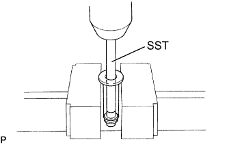
Using SST and a press, press out the sleeve plug assembly from the governor sleeve.
- SST
- 09236-00101 ( 09237-00070 )
-
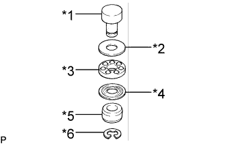
Text in Illustration *1 Sleeve Plug *2 Bearing Retainer *3 Bearing *4 Bearing Retainer *5 Stop Ring *6 E-Ring Remove the E-ring, stop ring, bearing and 2 bearing retainers from the sleeve plug.
-
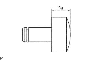
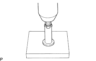
Text in Illustration *a Head Thickness Measure the head thickness of the sleeve plug, and select a new sleeve plug.
Governor sleeve plug head thickness: 3.0 mm (0.118 in.) 3.5 mm (0.138 in.) 4.0 mm (0.157 in.) 3.1 mm (0.122 in.) 3.6 mm (0.142 in.) 4.1 mm (0.161 in.) 3.2 mm (0.126 in.) 3.7 mm (0.146 in.) 4.2 mm (0.165 in.) 3.3 mm (0.130 in.) 3.8 mm (0.150 in.) - 3.4 mm (0.134 in.) 3.9 mm (0.154 in.) - Tech Tips
Lengthening the plug by 0.1 mm (0.004 in.) will decrease injection volume by 0.6 cc (0.04 cu in.). If the variation limit is greater than specified, replace the delivery valve.
-
Text in Illustration *1 New Sleeve Plug *2 Bearing Retainer *3 Bearing *4 Bearing Retainer *5 Stop Ring *6 New E-Ring Install the bearing, 2 retainers and stop ring to the new sleeve plug with a new E-ring.
-
Using a press, press in the sleeve plug assembly to the governor sleeve.
-
-
-
ADJUST LOAD SENSING TIMER (w/o ACSD)
-
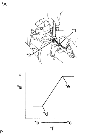
Text in Illustration *A w/o HAC *1 5 mm Hexagon Wrench *2 Governor Shaft *a Injection Pump Inner Pressure *b Idle Speed Side *c Maximum Speed Side *d End Point of Load Sensing Timer *e Starting Point of Load Sensing Timer *f Adjusting Lever Position Using a 5 mm hexagon wrench, adjust the starting and end points of the load sensing timer by turning the governor shaft.
-
Set the adjusting lever to the maximum position.
-
Measure the injection volume.
Injection volume (Part No. 22100-5D230, 22100-5D250) Adjusting lever position Pump rpm No. of measuring strokes Maximum speed side 1200 200 -
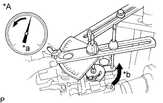
Text in Illustration *A w/o HAC *a kg/cm2
*b Slowly Move Slowly move the adjusting lever from the maximum speed side to the idle speed side, and secure it at the point where the pump inner pressure begins to drop.
-
Measure the injection volume at the drop point (starting point).
Injection volume (Part No. 22100-5D230, 22100-5D250) Pump rpm No. of measuring strokes Injection volume of each cylinder cc (cu in.) 1200 200 Measured value at step (d) minus 1.2 (0.07) to 2.0 (0.12) -
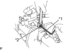
Text in Illustration *1 5 mm Hexagon Wrench *2 Governor Shaft Using a 5 mm hexagon wrench, adjust the load sensing timer by turning the governor shaft, and perform the measurement again as specified.
Tech Tips
The injection volume will increase approximately 3 cc (0.2 cu in.) with each 1/2 turns of the governor shaft.
-
Text in Illustration *A w/o HAC *a kg/cm2
*b Stop *c Slowly Move Check the end point injection volume by slowly moving the adjusting lever from the maximum speed side to the idle speed side, and secure it at the point where the pump inner pressure stops dropping.
Injection volume (Part No. 22100-5D230, 22100-5D250) Pump rpm No. of measuring strokes Injection volume of each cylinder cc (cu in.) 1200 200 9.58 to 9.98 (0.59 to 0.61) -
Text in Illustration *A w/o HAC *a Move 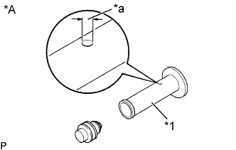
Text in Illustration *A w/o HAC *1 Governor Sleeve *a Hole Diameter Check the timer piston fluctuation when the adjusting lever is moved from the maximum speed side to the idle speed side.
Timer piston fluctuation (Part No. 22100-5D230, 22100-5D250) Pump rpm Timer piston fluctuation mm (in.) 1200 0.82 to 1.22 (0.0323 to 0.0480) If the timer stroke is not as specified when the load sensing is at maximum retard angle, select a new governor sleeve.
Governor sleeve hole diameter: 0.90 mm (0.0354 in.) 0.95 mm (0.0374 in.) 1.00 mm (0.0394 in.) Tech Tips
A large hole diameter decreases the timer stroke but a smaller hole diameter increases the timer stroke.
-
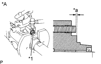
Text in Illustration *A w/o HAC *1 Governor Shaft *a 0.5 to 2.0 mm Check the protrusion of the governor shaft.
Protrusion (Part No. 22100-5D230, 22100-5D250) 0.5 to 2.0 mm (0.020 to 0.079 in.)
-
-
ADJUST IDLE SPEED
-
Measure the injection volume for each pump rpm.
Injection volume w/ ACSD (Part No. 22100-5D320) Adjusting lever angle Pump rpm No. of measuring strokes Injection volume of each cylinder cc (cu in.) Variation limit cc (cu in.) Remark Minus 12.5 to 22.5° 350 200 2.86 to 3.86 (0.17 to 0.24) 0.34 (0.02) Adjust 575 200 2.6 (0.16) or less - - w/o ACSD (Part No. 22100-5D110, 22100-5D230, 22100-5D250) Adjusting lever angle Pump rpm No. of measuring strokes Injection volume of each cylinder cc (cu in.) Variation limit cc (cu in.) Remark Minus 11.5 to 21.5° 350 200 3.7 to 4.7 (0.23 to 0.29) 0.34 (0.02) Adjust 575 200 2.4 (0.15) or less - - -
Text in Illustration *1 Idle Speed Adjusting Screw Adjust injection volume by turning the idle speed adjusting screw.
-
-
ADJUST FAST IDLE SPEED (w/ ACSD)
-
Release the cold starting system.
-
Using a screwdriver, turn the cold starting lever by approximately 20° counterclockwise.
-
Text in Illustration *A w/ ACSD *1 Metal Plate *a Turn Put a metal plate (thickness of 8.5 to 10.0mm(0.335 to 0.394 in.)) between the cold starting lever and thermo wax plunger.
-
-
Set the adjusting lever to the idle position.
-
Measure the injection volume.
Injection volume (Part No. 22100-5D320) Pump rpm No. of measuring strokes Injection volume of each cylinder cc (cu in.) 350 200 q = 2.86 to 3.86 (0.17 to 0.24) -
Remove the metal plate between the cold starting lever and thermo wax plunger.
-
Text in Illustration *A w/ ACSD *a 4.9 N*m Torque the cold starting lever clockwise to approximately 4.9 N*m (50 kgf*cm, 43 in.*lbf) and keep the lever tightened for about 10 seconds. Then release the torque.
-
Measure the injection volume.
Injection volume (Part No. 22100-5D320) Pump rpm No. of measuring strokes Injection volume of each cylinder cc (cu in.) 350 200 q plus 0.52 to 0.72 (0.03 to 0.04) -
Text in Illustration *A w/ ACSD *1 First Idle Adjusting Screw Adjust the injection volume by turning the fast idle adjusting screw.
-
-
POST ADJUSTMENT CHECK
-
Text in Illustration *A w/ ACSD *1 Metal Plate *a Turn Check the injection stops when the fuel cut solenoid harness is removed.
Pump revolution 100 rpm -
w/ ACSD:
Release the cold starting system.
-
Using a screwdriver, turn the cold starting lever by approximately 20° counterclockwise.
-
Put a metal plate (thickness of 8.5 to 10.0mm(0.335 to 0.394 in.)) between the cold starting lever and thermo wax plunger.
-
-
Text in Illustration *a Move Check the adjusting lever movement.
w/ ACSD 41 to 51° w/o ACSD 42 to 48° -
w/ ACSD:
Remove the metal plate between the cold starting lever and thermo wax plunger.
-
-
INSTALL THROTTLE POSITION SENSOR (w/ EGR)
-
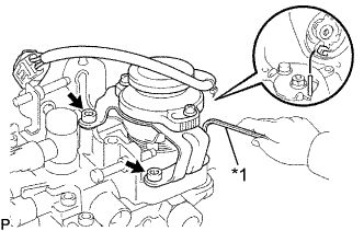
Text in Illustration *1 5 mm Hexagon Wrench Attach the portions of the throttle position sensor and adjusting lever.
-
Using a 5mm hexagon wrench, install the throttle position sensor with the 3 bolts.
- Torque:
- 8.35 N*m { 85 kgf*cm, 74 in.*lbf }
-
-
ADJUST THROTTLE POSITION SENSOR
-
Set the adjusting lever to the angle for the injection volume shown below.
Pump rpm No. of measuring strokes Injection volume of each cylinder cc (cu in.) 1500 200 5.92 to 6.08 (0.36 to 0.37) -
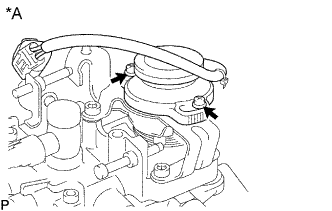
Text in Illustration *A w/ EGR Loosen the 2 screws holding the throttle position sensor to the bracket.
-
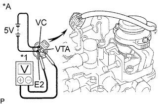
Text in Illustration *A w/ EGR *1 Voltmeter Apply 4.995 to 5.005 V across terminals VC and E2.
-
Connect the tester probes of a voltmeter to terminals VTA and E2 of the throttle position sensor.
-
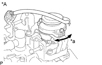
Text in Illustration *A w/ EGR *a Turn Gradually turn the throttle position sensor so that its output will be 2.376 to 2.424 V.
-
Tighten the 2 screws holding the throttle position sensor to the bracket.
-
-
REMOVE INJECTION PUMP FROM TESTER
-
SEAL PARTS
-
Text in Illustration *1 Maximum Speed Adjusting Screw *2 Full Load Set Screw Seal the full load set screw and maximum speed adjusting screw with new lead seals.
-