FUEL INJECTION PUMP DISASSEMBLY

Note
w/ HAC:
When re-using the governor cover assembly, to prevent oil spilling out from the bushing of the governor cover when doing steps 1 to 11, removal and installation should be done without tilting it by 45°or more from the horizontal.
-
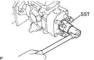
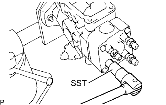
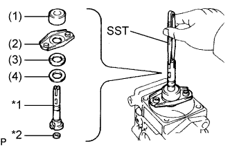
MOUNT PUMP ASSEMBLY TO SST (STAND)
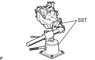
- SST
- 09241-76022
- 09245-54010
-
REMOVE SET KEY OF INJECTION PUMP DRIVE PULLEY ON DRIVE SHAFT
-
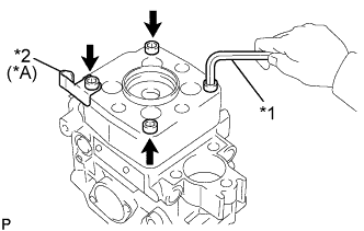
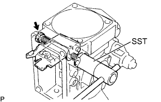
REMOVE THROTTLE POSITION SENSOR (w/ EGR)
-
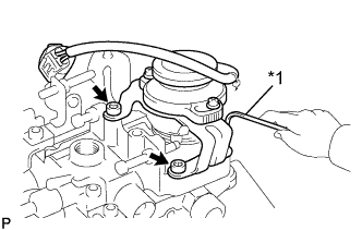
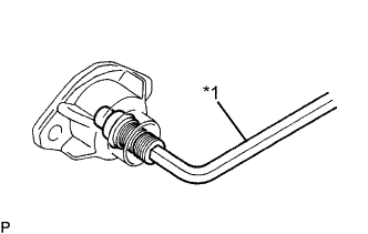
Text in Illustration *1 5 mm Hexagon Wrench Using a 5 mm hexagon wrench, remove the 3 bolts and throttle position sensor.
-
-
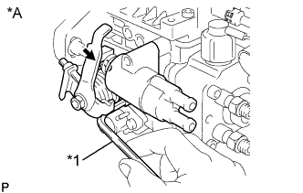
REMOVE IDLE-UP SUB-ASSEMBLY
-
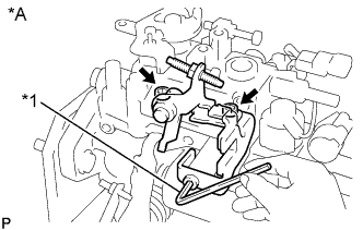
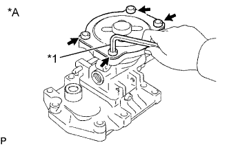
Text in Illustration *A w/ ACSD *1 5 mm Hexagon Wrench Using a 5 mm hexagon wrench, remove the 3 bolts and idle-up sub-assembly.
-
-
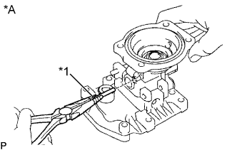
REMOVE TIMER COVER SUB-ASSEMBLY (THERMO WAX) (w/ ACSD)
-
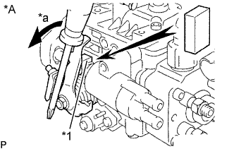
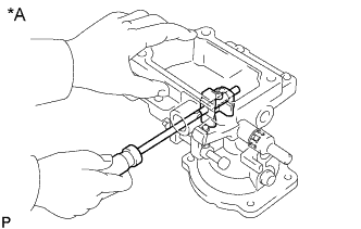
Text in Illustration *A w/ ACSD *1 Metal Plate *a Turn Using a screwdriver, turn the cold starting lever by approximately. 20°counterclockwise.
-
Put a metal plate (thickness of 8.5 to 10.0 mm (0.335 to 0.394 in.)) between the cold starting lever and thermo wax plunger.
-
Text in Illustration *A w/ ACSD *1 5 mm Hexagon Wrench Using a 5 mm hexagon wrench, remove the 2 bolts, thermo wax and gasket.
-
-
REMOVE TIMING CONTROL VALVE (w/ TCV)
-
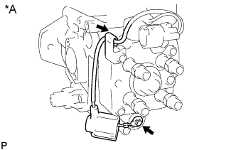
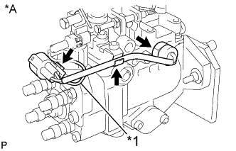
Text in Illustration *A w/ TCV Disconnect the dust cover from the timing control valve.
-
Remove the nut, and disconnect the lead wire from the timing control valve.
-
Disconnect the lead wire from the lead clamp on the distributive head.
-
Text in Illustration *A w/ TCV *1 5 mm Hexagon Wrench Using a 5mm hexagon wrench, remove the 3 bolts, timing control valve, strainer and wave washer.
-
Remove the 2 O-rings from the timing control valve.
-
-
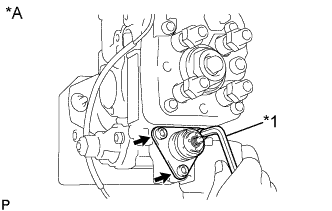
REMOVE ENGINE SPEED SENSOR
-
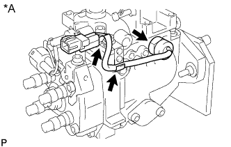
Text in Illustration *A w/ TCV w/ TCV:
Disconnect the lead wire and connector from the lead clamp on the governor cover.
-
Remove the pickup sensor and O-ring.
-
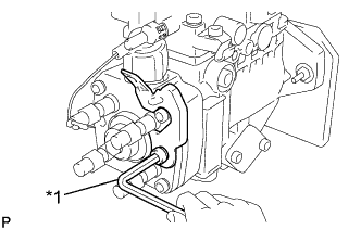
Text in Illustration *A w/o TCV *1 Lead Wire w/o TCV:
Disconnect the lead wire from the lead clamp on the governor cover.
-
w/o TCV:
Disconnect the connector from the connector bracket on the distributive head.
-
w/o TCV:
Disconnect the lead wire for fuel cut solenoid from the connector.
-
Remove the engine speed sensor and O-ring.
-
-
REMOVE CONNECTOR BRACKET
-
Text in Illustration *1 6 mm Hexagon Wrench Using a 6 mm hexagon wrench, remove the bolt and connector bracket.
-
-
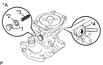
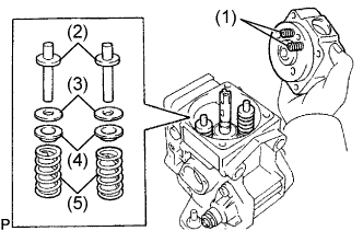
REMOVE FUEL CUT SOLENOID ASSEMBLY
-
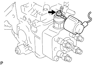
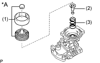
Disconnect the dust cover from the fuel cut solenoid.
-
Remove the nut and lead wire.
-
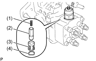
Remove the fuel cut solenoid, O-ring, spring (1), valve (2), strainer (3) and wave washer (4).
-
-
REMOVE ADJUSTING LEVER SUB-ASSEMBLY
-
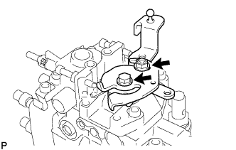
Remove the bolt, nut, No. 1 and No. 2 adjusting levers and return spring.
-
-
REMOVE GOVERNOR COVER SUB-ASSEMBLY
-
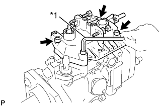
Text in Illustration *1 5 mm Hexagon Wrench w/ HAC:
Remove the idle speed adjusting screw.
-
Using a 5 mm hexagon wrench, remove the 4 bolts.
-
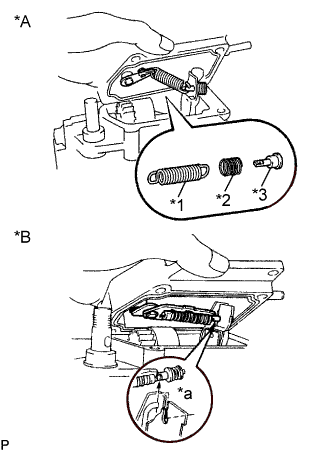
Text in Illustration *A M/T *B A/T *1 Speed Control Spring *2 Damper Spring *3 Spring Seat *a Disconnect Disconnect the adjusting lever shaft from the governor cover, and remove the governor cover and gasket.
-
M/T:
Remove the adjusting lever shaft, speed control spring, spring seat and damper spring from the governor link.
-
A/T:
Disconnect the adjusting lever shaft from the governor link, and remove the adjusting lever shaft.
-
Remove the O-ring and plate washer from the adjusting lever shaft.
Note
w/ HAC:
After removing the governor cover assembly, do not place it at an angle of 45°or more from the horizontal.
-
-
REMOVE HIGH ALTITUDE COMPENSATOR (w/ HAC:)
-
Text in Illustration *A w/ HAC *1 Bolt *2 Gasket *3 Lever Control Spring *4 Rubber Cap Remove lever control spring.
Remove the bolt, gasket and lever control spring.
-
Remove rubber cap.
-
Text in Illustration *A w/ HAC *1 5 mm Hexagon Wrench Remove the pneumatic bellows.
-
Using a 5 mm hexagon wrench, remove the 4 bolts, pneumatic bellows cover and gasket.
-
Text in Illustration *A w/ HAC Remove the pneumatic bellows and 2 rubber caps (1), push rod (2) and pneumatic bellows spring (3).
-
-
Remove the control lever.
-
Text in Illustration *A w/ HAC *1 4 mm Hexagon Wrench Using a 4 mm hexagon wrench, remove the 2 bolts and gaskets.
-
Text in Illustration *A w/ HAC Using a small screwdriver, push out the support pin and remove the control lever.
-
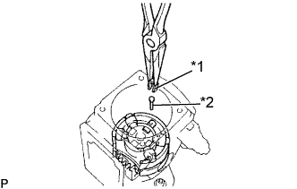
Text in Illustration *A w/ HAC *1 Tape Using needle nose pliers, remove the connecting pin.
Note
Be careful not to damage the connecting pin. Tape the tip of the pliers.
-
-
-
REMOVE GOVERNOR SHAFT AND FLYWEIGHT HOLDER
-
Check the flyweight holder thrust clearance Click here.
-
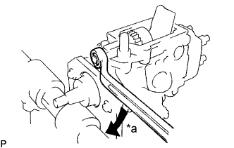
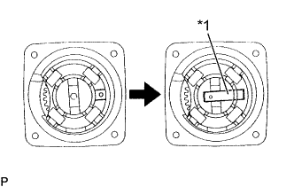
Text in Illustration *a Turn Remove the governor shaft lock nut by turning it clockwise.
Note
The governor shaft and lock nut have LH threads.
-
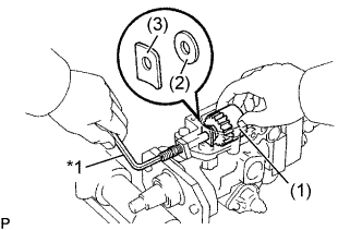
Text in Illustration *1 5 mm Hexagon Wrench Using a 5 mm hexagon wrench, remove the governor shaft clockwise, and remove the flyweight holder assembly (1), No. 1 flyweight washer (2) and governor gear adjusting washer (3).
Note
Be careful not to drop the 2 washers into the pump housing.
-
Remove the O-ring from the governor shaft.
-
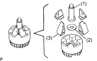
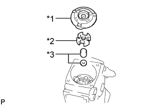
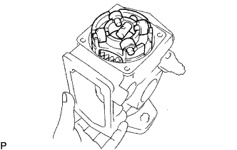
Remove the governor sleeve (1) No. 2 flyweight washer (2) and 4 flyweights (3) from the flyweight holder.
-
-
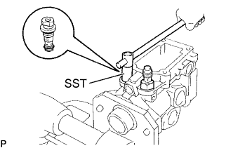
REMOVE DISTRIBUTIVE HEAD PLUG
-
Using SST, remove the distributive head plug and O-ring.
- SST
- 09260-54012 ( 09262-54010 )
-
-
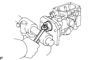
REMOVE INJECTION PUMP DELIVERY VALVE SUB-ASSEMBLY
-
Using SST, remove the 4 delivery valve holders and springs.
- SST
- 09260-54012 ( 09269-54020 )
-
Remove the 4 delivery valves and gaskets.
Note
Do not touch the sliding surfaces of the delivery valve by hand.
Tech Tips
Arrange the delivery valves, springs, and holders in order.
-
-
REMOVE DISTRIBUTIVE PUMP HEAD SUB-ASSEMBLY
-
Text in Illustration *A (w/ TCV) *1 5mm Hexagon Wrench *2 Clamp Using a 5 mm hexagon wrench, remove the 4 bolts and lead clamp (w/ TCV).
-
Remove the distributive head and 2 lever support springs (1), 2 plunger spring guides (2), 2 plunger spring shims (3), 2 upper spring seats (4) and 2 plunger springs (5).
-
Remove the O-ring from the distributive head.
-
-
REMOVE PUMP PLUNGER
-
Text in Illustration *1 Plunger *2 Shim Using SST, remove the pump plunger and plunger adjusting shim together with the spill ring (1), lower spring seat (2), upper plunger plate (3) and lower plunger plate (4).
- SST
- 09260-54012 ( 09269-54030 )
Note
Do not touch the sliding surfaces of the pump plunger by hand.
-
-
REMOVE GOVERNOR LINK
-
Using SST, remove the 2 support bolts, 2 gaskets and governor link.
- SST
- 09260-54012 ( 09269-54040 )
-
-
REMOVE FACE CAMPLATE
-
Text in Illustration *1 Face Camplate *2 Coupling *3 Spacer Remove the face camplate, coupling and spacers.
-
-
REMOVE ROLLER RING AND DRIVE SHAFT
-
Text in Illustration *1 Clip *2 Stopper Pin Remove the clip and stopper pin.
-
Text in Illustration *1 Slide Pin Push the slide pin toward inside.
-
Push the drive shaft, and remove the roller ring, 4 rollers and washers assembly.
Note
-
Be careful not to drop the rollers.
-
Do not alter the position or assembly of the rollers.
-
-
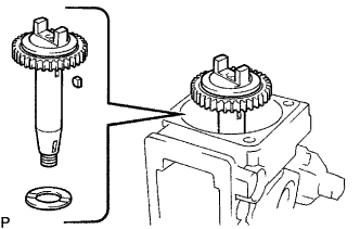
Remove the drive shaft, governor drive gear, 2 joint rubbers assembly, set key and drive shaft washer.
-
Remove the drive gear and 2 joint rubbers from the drive shaft.
-
-
REMOVE TIMER PISTON ASSEMBLY
-
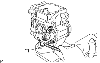
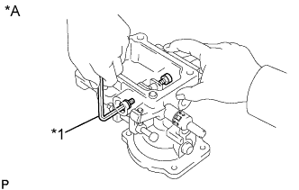
Text in Illustration *1 5 mm Hexagon Wrench Using a 5 mm hexagon wrench, remove the 2 LH timer cover bolts.
-
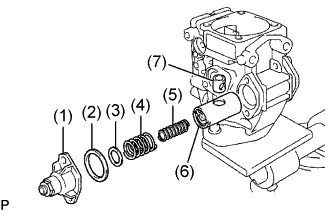
Remove the LH timer cover, timer adjusting screw, nut assembly (1), gasket (2), spring washer (3), timer outer spring (4), timer inner spring (5), timer piston (6) and timer sub-piston (7).
-
Text in Illustration *1 5 mm Hexagon Wrench Remove the nut from the LH timer cover.
-
Using a 5 mm hexagon wrench, remove the timer adjusting screw.
-
Remove the O-ring from the timer adjusting ring.
-
Text in Illustration *1 5 mm Hexagon Wrench Using a 5 mm hexagon wrench, remove the 2 bolts, RH timer cover and O-ring.
-
-
REMOVE FUEL FEED PUMP SUB-ASSEMBLY
-
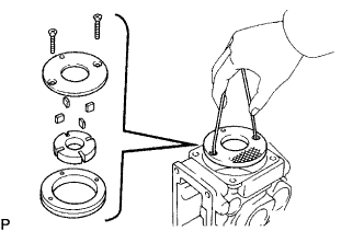
Remove the 2 screws.
-
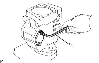
Using a piece of wire, remove the feed pump cover.
-
Remove the feed pump rotor, 4 blades and liner.
Note
-
Be careful not to interchange the blade positions.
-
Be careful not to damage the pump body.
-
-
-
REMOVE REGULATOR VALVE SUB-ASSEMBLY
-
Using SST, remove the regulator valve and 2 O-rings.
- SST
- 09260-54012 ( 09262-54020 )
-
-
REMOVE FUEL INLET HOLLOW SCREW
-
Remove the hollow screw and gasket.
-
-
REMOVE OIL SEAL
-
Using a wrench, pry out the oil seal.
-