SUCTION CONTROL VALVE (w/ DPF) INSTALLATION
-
INSTALL SUCTION CONTROL VALVE ASSEMBLY
Note
-
Before replacing the suction control valve, be sure to clean the surrounding area.
-
When replacing the suction control valve, make sure that your hands are clean and do not use gloves, etc.
-
Apply engine oil to a new O-ring.
Note
Be sure to use clean engine oil.
-
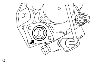
Install the O-ring to the O-ring groove of the injection pump.
Note
Make sure that the O-ring and O-ring groove are free of foreign matter and are not damaged.
-
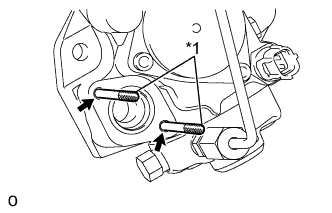
Text in Illustration *1 Guide Pin Install guide pins used for the insertion of the suction control valve to the bolt holes.
Tech Tips
-
When installing the guide pins, it is sufficient to fix them lightly in place by hand.
-
The guide pins are used to make sure that the suction control valve remains perpendicular to the injection pump when it is inserted.
-
-
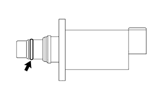
Apply engine oil to the O-ring at the end of the suction control valve.
Note
Be sure to use clean engine oil.
-
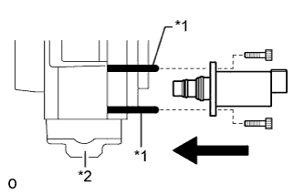
Text in Illustration *1 Guide Pin *2 Injection Pump While making sure that the suction control valve and injection pump remain perpendicular to each other, slide the suction control valve along the guide pins and insert it into the injection pump as shown in the illustration.
Note
-
Make sure that the contact surfaces of the injection pump and suction control valve are free of foreign matter and are not damaged.
-
Do not insert the suction control valve at an angle.
-
Make sure that the O-ring does not get pinched between the parts. If it does, replace it with a new one.
-
Insert the suction control valve until it contacts the injection pump.
-
-
While holding the suction control valve in place, remove the guide pins, temporarily install 2 new bolts and uniformly tighten them by hand.
Note
Do not use tools. Tighten the bolts by hand until the surfaces of the suction control valve and injection pump contact each other.
-
Using a 5 mm hexagon wrench, uniformly tighten the 2 bolts.
- Torque:
- 9.0 N*m { 92 kgf*cm, 80 in.*lbf }
-
Connect the connector to the suction control valve.
Note
Make sure that there is not excessive slack or tension in the wire harness of the suction control valve.
-
-
INSTALL SUPPLY PUMP ASSEMBLY
-
SUPPLY PUMP ASSEMBLY INITIALIZATION
-
INSPECT FOR FUEL LEAK
-
Perform the Active Test.
-
Connect the intelligent tester to the DLC3.
-
Turn the ignition switch to ON.
-
Turn the intelligent tester on.
-
Enter the following menus: Powertrain / Engine and ECT / Active Test.
-
Perform the Active Test.
Intelligent Tester Display Test Part Control Range Diagnostic Note Test the Fuel Leak Pressurize the common rail interior and check for fuel leaks Stop/Start
-
Fuel pressure inside common rail pressurized to specified value and engine speed increased to 2000 rpm when ON is selected.
-
Above conditions preserved while test is ON
Tech Tips
If this Active Test is performed when the engine is cold, combustion may become unstable. However, this is not a malfunction. It is only necessary to confirm that the pressure rises to the target pressure and that there are no fuel leaks.
-
-
-