FUEL SUPPLY PUMP (w/ DPF) REMOVAL

Note
-
When replacing the injectors (including shuffling the injectors between the cylinders), common rail or cylinder head, it is necessary to replace the injection pipes with new ones.
-
When replacing the fuel supply pump, common rail, cylinder block, cylinder head, cylinder head gasket or timing gear case, it is necessary to replace the fuel inlet pipe with a new one.
-
After removing the fuel inlet pipe, clean it with a brush and compressed air.
-
DISCONNECT CABLE FROM NEGATIVE BATTERY TERMINAL
-
REMOVE TIMING BELT
-
REMOVE EGR COOLER ASSEMBLY
-
REMOVE VANE PUMP ASSEMBLY
-
REMOVE NO. 3 NOZZLE LEAKAGE PIPE
-
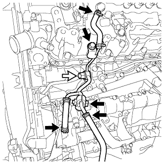
Disconnect the 3 fuel hoses.
-
Remove the fuel check valve and gasket from the No. 3 nozzle leakage pipe.
Text in Illustration 
Fuel Check Valve -
Remove the bolt and No. 2 injection pipe clamp from the No. 3 nozzle leakage pipe and No. 3 fuel pipe.
-
Remove the bolt and No. 3 nozzle leakage pipe.
-
-
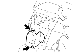
REMOVE NO. 2 EXHAUST MANIFOLD HEAT INSULATOR
-
Remove the 2 bolts and No. 2 exhaust manifold heat insulator.
-
-
REMOVE NO. 3 FUEL PIPE
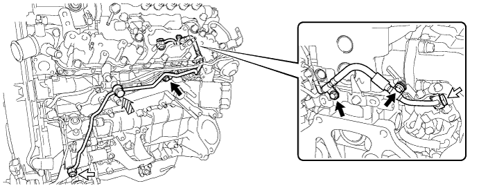
Text in Illustration Union Bolt 
Fuel Check Valve 
Bolt - -
-
Remove the 2 union bolts and gasket from the No. 3 fuel pipe.
-
Remove the fuel check valve and gasket from the No. 3 fuel pipe.
-
Remove the 3 bolts and No. 3 fuel pipe.
-
-
REMOVE PUMP DRIVE SHAFT PULLEY
-
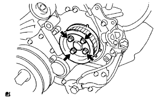
Remove the 4 bolts indicated by the arrows in the illustration.
-
Remove the No. 2 camshaft timing pulley flange and pump drive shaft pulley.
-
-
REMOVE FUEL SUPPLY PUMP ASSEMBLY
-
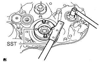
Using SST, remove the nut and O-ring while holding the crankshaft pulley.
- SST
- 09213-58014
- 09330-00021
-
Disconnect the fuel temperature sensor connector and suction control valve connector from the fuel supply pump.
-
Disconnect the fuel hose.
-
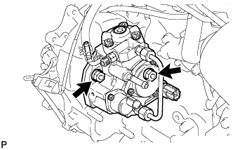
Loosen the 2 nuts.
-
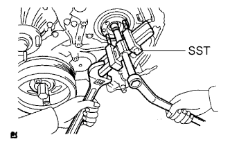
Using SST, disconnect the fuel supply pump assembly from the injection gear.
- SST
- 09950-50013 ( 09951-05010, 09952-05010, 09953-05020, 09954-05021 )
Note
Apply lubricant to the threads and tip of SST (center bolt) before using it.
-
Remove the 2 nuts and fuel supply pump.
Note
-
Do not hold or carry the fuel supply pump by the pipe.
-
The fuel supply pump must be kept horizontal.
-
-
Remove the O-ring from the fuel supply pump assembly.
-