FUEL INJECTOR (w/o DPF) INSTALLATION

-
INSTALL FUEL INJECTOR
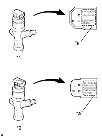
Text in Illustration *1 #1, #2 Cylinder *2 #3, #4 Cylinder *a Injector Compensation Code Note
-
Register the injector compensation code in the ECM when replacing the fuel injector with a new one. Record the injector compensation code of the fuel injector and keep them in the correct order so that they can be easily installed.
-
The connector shape of cylinders (#1, #2) is different from that of the cylinders (#3, #4).
-
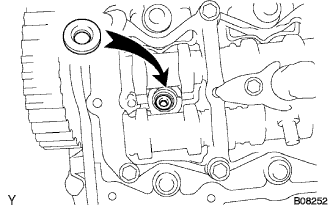
Install a new injection nozzle seat to the cylinder head.
-
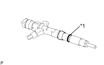
Text in Illustration *1 O-Ring Apply a small amount of engine oil to a new O-ring and install it to the fuel injector.
-
Install the fuel injector to the cylinder head.
Note
When reusing a fuel injector, install the same fuel injector that was removed. Otherwise, it could cause the engine to malfunction.
-
Temporarily install injection pipe sub-assemblies No. 1, No. 2, No. 3 and No. 4.
Note
When replacing the fuel injector, common rail, or cylinder head with a new one, replace injection pipe sub-assemblies No. 1, No. 2, No. 3 and No. 4.
-
Apply engine oil to the union bolt and screw portion of the injector hollow screw.
-
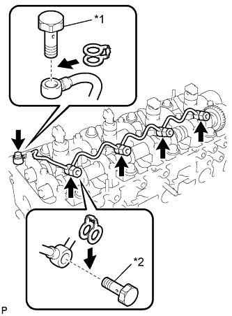
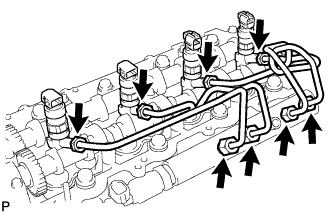
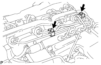
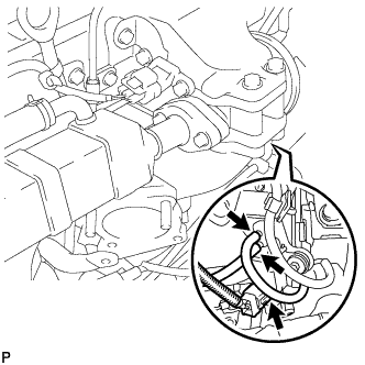
Text in Illustration *1 Union Bolt *2 Hollow Screw Temporarily install the nozzle leakage pipe assembly through a new gasket with the union bolt and 4 injector hollow screws.
-
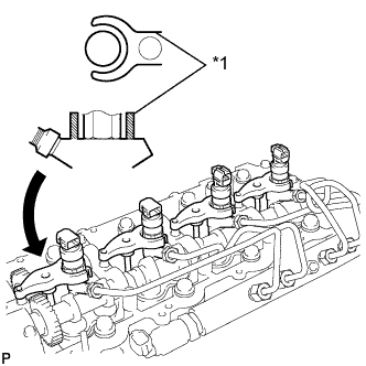
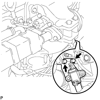
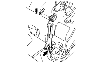
Text in Illustration *1 Nozzle Clamp Holder Using the fork part of the nozzle holder clamp, clamp the fuel injector in place with the bolt of the camshaft bearing cap as a fulcrum.
-
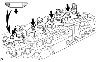
Install the nozzle holder clamp with a new washer and bolt.
- Torque:
- 22 N*m { 220 kgf*cm, 16 ft.*lbf }
Note
This washer is directional.
-
Remove injection pipe sub-assemblies No. 1, No. 2, No. 3 and No. 4.
-
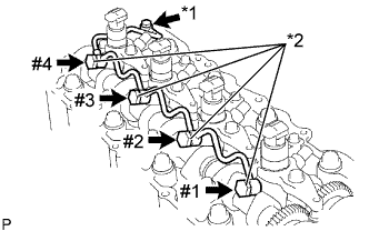
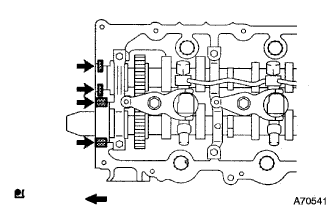
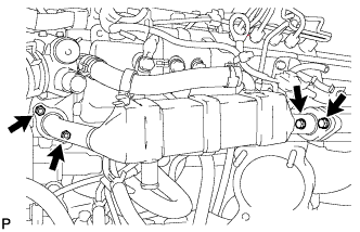
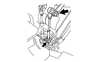
Text in Illustration *1 Union Bolt *2 Hollow Screw Tighten the injector hollow screws in the following sequence: #1, #2, #3 and #4.
- Torque:
- 16 N*m { 163 kgf*cm, 12 ft.*lbf }
Note
When the screws are excessively tightened, replace the nozzle leakage pipe assembly with a new one.
-
Tighten the union bolt to the specified torque.
- Torque:
- 13 N*m { 127 kgf*cm, 9 ft.*lbf }
Note
When the bolt is excessively tightened, replace the leakage pipe assembly with a new one.
-
-
INSPECT FOR NOZZLE LEAKAGE PIPE ASSEMBLY LEAK
-
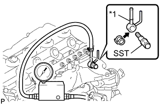
Text in Illustration *1 Nozzle Leakage Pipe No. 2 Install nozzle leakage pipe No. 2 and SST through a new gasket.
- SST
- 09280-00010
- Torque:
- 21 N*m { 214 kgf*cm, 16 ft.*lbf }
Nozzle Leakage Pipe No. 2 Part No. 23762 - 27010 -
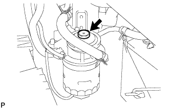
Connect the hose of the turbo charge pressure gauge to nozzle leakage pipe No. 2.
-
Pressurize the turbo charge pressure gauge to 250kPa (2.5kfg/cm, 36psi).
-
Maintain the pressure at 250kPa for 60 seconds and check the installation portion of the nozzle leakage pipe assembly for air leakage.
Note
Do not pressurize the pipe to more than 250kPa. Excessively high air pressure may cause air leakage on the high pressure side.
Tech Tips
-
Apply engine oil to the installation portion of the nozzle leakage pipe assembly and check that no bubbles are formed.
-
Make sure that the turbo charge pressure gage reading remains constant.
-
-
Remove the turbo charge pressure gauge and SST.
-
-
INSTALL CYLINDER HEAD COVER SUB-ASSEMBLY
-
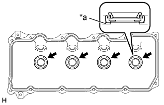
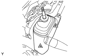
Text in Illustration *a Upper Side of Cylinder Head Cover Sub-assembly Install 4 new No. 3 cylinder head cover gaskets to the cylinder head cover sub-assembly as shown in the illustration.
Note
-
Do not install the gaskets at an angle.
-
Keep the lip of the gasket free from foreign materials.
-
-
Install a new cylinder head cover gasket to the cylinder head cover sub-assembly.
-
Apply a seal packing to the cylinder head as shown in the illustration.
Seal packing Toyota Genuine Seal Packing Black, Three Bond 1207B or equivalent Note
-
Remove any old oil from the contact surface.
-
If the cylinder head cover gasket is cracked or damaged, replace it with a new one.
-
Assemble parts within 3 minutes and tighten them within 15 minutes of applying the seal packing.
-
-
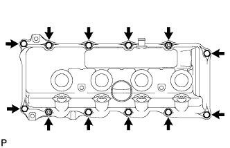
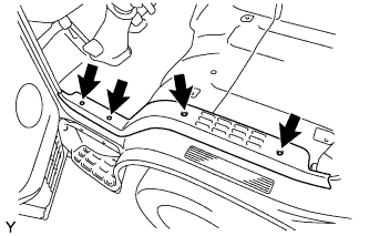
Install the cylinder head cover sub-assembly with 10 bolts and 2 nuts.
- Torque:
- 9.0 N*m { 92 kgf*cm, 80 in.*lbf }
-
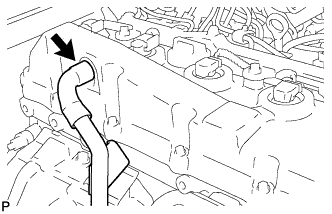
Connect the ventilation hose.
-
Install 4 new nozzle holder seals to the cylinder head cover sub-assembly.
-
-
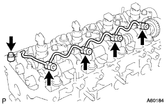
INSTALL INJECTION PIPE SUB-ASSEMBLY
Note
When replacing the fuel injector, common rail, or cylinder head with a new one, replace injection pipe sub-assemblies No. 1, No. 2, No. 3 and No. 4.
-
Temporarily install the injection pipe sub-assembly.
-
Install the 2 injection pipe clamp No. 2 with the 2 bolts.
- Torque:
- 5.0 N*m { 51 kgf*cm, 44 in.*lbf }
-
Using union nut wrench 17 mm, tighten the union nut on the fuel injector side to the specified torque.
- Torque:
- 35 N*m { 357 kgf*cm, 26 ft.*lbf }
Note
Use the formula to calculate special torque values for situations where a union nut wrench is combined with a torque wrench Click here.
-
Using union nut wrench 17 mm, tighten the union nut on the common rail side to the specified torque.
- Torque:
- 35 N*m { 357 kgf*cm, 26 ft.*lbf }
Note
Refer to the torque above when not using SST. When using SST, calculate the torque in accordance with the lengths of SST and the torque wrench Click here.
-
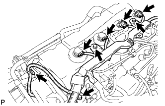
Install the wire harness with the 3 bolts.
- Torque:
- 8.0 N*m { 82 kgf*cm, 71 in.*lbf }
-
Connect the fuel injector connector and harness clamp.
-
-
INSTALL NO. 2 NOZZLE LEAKAGE PIPE ASSEMBLY
-
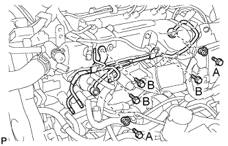
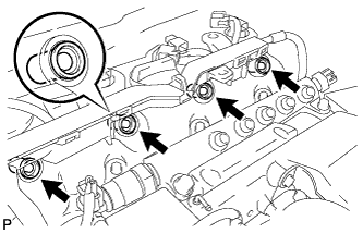
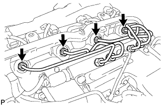
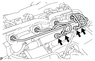
Temporarily install nozzle leakage pipe assembly No. 2 through a new gasket with the 2 union bolts and 3 bolts.
-
Tighten the 2 union bolts and 3 bolts to the specified torque.
- Torque:
- 21 N*m { 214 kgf*cm, 16 ft.*lbf, for bolt A }
- 13 N*m { 129 kgf*cm, 9 ft.*lbf, for bolt B }
-
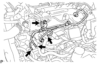
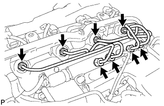
Connect the 4 fuel hoses to the No. 2 nozzle leakage pipe assembly.
-
-
INSTALL FUEL INLET PIPE SUB-ASSEMBLY
Note
When replacing the fuel supply pump, common rail, cylinder block, cylinder head, cylinder head gasket, or timing gear case with a new one, replace the fuel inlet pipe sub-assembly.
-
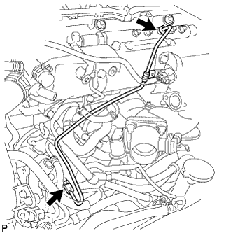
Temporarily install the fuel inlet pipe sub-assembly.
-
Text in Illustration *1 No. 1 Clamp *2 No. 2 Clamp Connect the No. 1 injection pipe clamp with the bolt.
- Torque:
- 5.0 N*m { 51 kgf*cm, 44 in.*lbf }
-
Install the No. 2 injection pipe clamp with the bolt.
- Torque:
- 5.0 N*m { 51 kgf*cm, 44 in.*lbf }
-
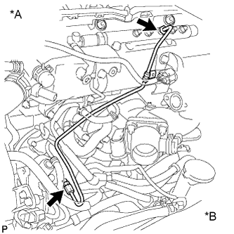
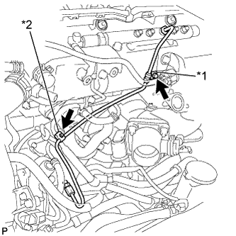
Text in Illustration *A Common Rail Side *B Supply Pump Side Using union nut wrench 17mm, tighten the union nut on the common rail side to the specified torque.
- Torque:
- 35 N*m { 357 kgf*cm, 26 ft.*lbf }
Note
Use the formula to calculate special torque values for situations where a union nut wrench is combined with a torque wrench Click here.
-
Using union nut wrench 17 mm, tighten the union nut on the supply pump to the specified torque.
- Torque:
- 35 N*m { 357 kgf*cm, 26 ft.*lbf }
Note
Use the formula to calculate special torque values for situations where a union nut wrench is combined with a torque wrench Click here.
-
-
INSTALL OIL LEVEL GAGE GUIDE (for RHD)
-
Apply a small amount of engine oil to a new O-ring and install it to the oil level gage guide.
-
Install the oil level gage guide with the bolt.
- Torque:
- 8.0 N*m { 82 kgf*cm, 71 in.*lbf }
-
Install the oil level gage sub-assembly.
-
-
TEMPORARILY TIGHTEN ELECTRIC EGR CONTROL VALVE
-
Temporarily install the electric EGR control valve.
-
Temporarily install the electric EGR control valve to the intake air connector with a new gasket.
-
Temporarily install the electric EGR control valve and intake air connector with the bolt and 2 nuts.
-
Temporarily install the manifold stay with the bolt.
-
Connect the vacuum hose to the intake air connector.
-
-
-
TEMPORARILY TIGHTEN EGR COOLER ASSEMBLY
-
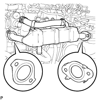
Temporarily install the EGR cooler assembly.
-
Temporarily install the EGR cooler assembly with 2 new gaskets with the 2 bolts and 2 nuts.
-
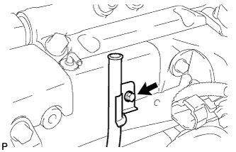
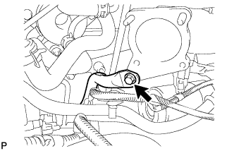
Temporarily install the bolt as shown in the illustration.
-
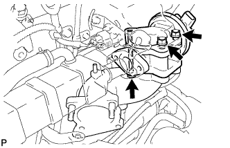
Tighten the 2 bolts and 2 nuts to the specified torque.
- Torque:
- 13 N*m { 133 kgf*cm, 10 ft.*lbf }
-
-
-
TIGHTEN ELECTRIC EGR CONTROL VALVE ASSEMBLY
-
Tighten the electric EGR control valve.
-
Tighten the bolt and 2 nuts to the specified torque.
- Torque:
- 20 N*m { 204 kgf*cm, 15 ft.*lbf }
-
-
Connect the intake air temperature sensor connector.
-
Connect the vacuum hose to the electric EGR control valve.
-
Connect the electric EGR control valve connector.
-
Install the vacuum regulating valve with bracket with the 2 bolts.
- Torque:
- 20 N*m { 204 kgf*cm, 15 ft.*lbf }
-
Connect the 2 vacuum hoses to the vacuum regulating valve.
-
Connect the vacuum regulating valve connector.
-
-
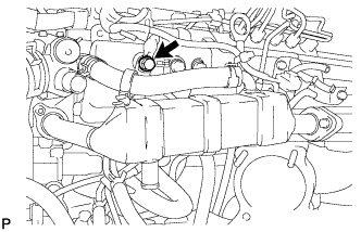
TIGHTEN EGR COOLER ASSEMBLY
-
Tighten the EGR cooler assembly.
-
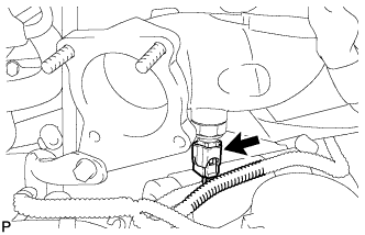
Tighten the bolt to the specified torque.
- Torque:
- 22 N*m { 224 kgf*cm, 16 ft.*lbf }
-
-
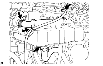
Install the water by-pass hose No. 2 with the clamp.
-
Install the water by-pass hose No. 4 with the clamp.
-
Install the oil return hose with the clamp.
-
-
INSTALL MANIFOLD STAY
-
Install the manifold stay.
-
Tighten the bolt to the specified torque.
- Torque:
- 19 N*m { 194 kgf*cm, 14 ft.*lbf }
-
-
-
INSTALL DIESEL THROTTLE BODY
-
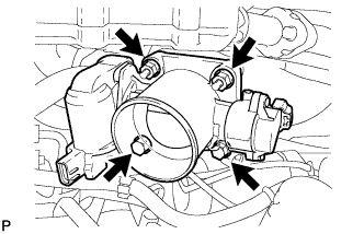
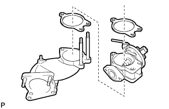
Install a new gasket to intake air connector.
-
Install the diesel throttle body with the 2 bolts and the 2 nuts.
- Torque:
- 20 N*m { 204 kgf*cm, 15 ft.*lbf }
-
Connect the 2 connectors.
-
-
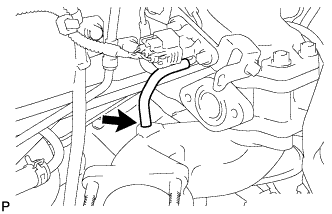
CONNECT NO. 3 AIR HOSE
-
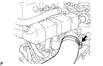
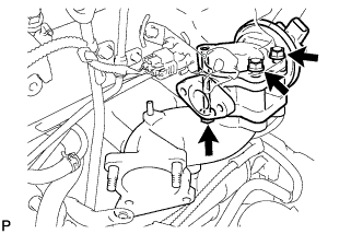
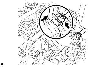
Connect the No. 3 air hose and secure the hose clamps as shown in the illustration.
-
-
INSTALL ENGINE SERVICE HOLE SUB COVER SUB-ASSEMBLY (for Double Cab)
-
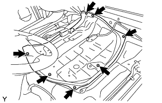
Install the engine service hole sub cover with the 7 bolts.
- Torque:
- 12 N*m { 120 kgf*cm, 9 ft.*lbf }
-
-
INSTALL PARKING BRAKE LEVER ASSEMBLY (for Double Cab)
-
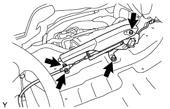
Install the parking brake lever with the 4 bolts.
- Torque:
- 17 N*m { 175 kgf*cm, 13 ft.*lbf }
-
Connect the connector.
-
-
INSTALL TRANSMISSION FLOOR SHIFT ASSEMBLY (for Double Cab)
-
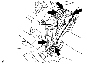
Install the transmission floor shift with the 4 bolts.
- Torque:
- 18 N*m { 185 kgf*cm, 13 ft.*lbf }
-
-
INSTALL FLOOR SHIFT CABLE TRANSMISSION CONTROL SHIFT (for Double Cab)
-
Install the floor shift cable transmission control select with clip and washer.
-
Install a new clip.
-
-
INSTALL FLOOR SHIFT CABLE TRANSMISSION CONTROL SELECT (for Double Cab)
-
Install the floor shift cable transmission control shift with the nut and washer.
- Torque:
- 12 N*m { 120 kgf*cm, 9 ft.*lbf }
-
Install a new clip.
-
-
INSTALL NO. 1 FRONT FLOOR MAT REAR (for Double Cab)
-
INSTALL FRONT FLOOR PANEL BRACE (for Double Cab)
-
Install the front floor panel brace with the 3 clips.
-
-
INSTALL SHIFT LEVER KNOB SUB-ASSEMBLY (for Double Cab)
-
INSTALL PARKING BRAKE HOLE COVER (for Double Cab)

-
Install the parking brake hole cover with the screw.
-
-
INSTALL FRONT DOOR SCUFF PLATE LH (for Double Cab)
-
Install the front door scuff plate LH with the 4 screws.
-
-
INSTALL FRONT SEAT ASSEMBLY LH (for Double Cab)
-
Install the front seat LH with the 4 bolts.
- Torque:
- 39 N*m { 400 kgf*cm, 29 ft.*lbf }
-
Connect the connector.
-
-
BLEED AIR FROM FUEL SYSTEM
-
Using the hand pump, bleed air from the fuel system until pumping becomes difficult.
-
-
CONNECT CABLE TO NEGATIVE BATTERY TERMINAL
- Torque:
- 6.4 N*m { 65 kgf*cm, 56 in.*lbf }
-
REGISTRATION INJECTOR COMPENSATION CODE
-
CHECK FOR INJECTOR COMPENSATION CODE
-
ADD ENGINE COOLANT
-
Pour coolant into the radiator until it overflows.
Capacity Specification Capacity w/o Heater 9.8 liters (10.3 US qts, 8.6 Imp. qts) w/ Front Heater 10.7 liters (11.3 US qts, 9.4 Imp. qts) w/ Front and Rear Heater 11.5 liters (12.2 US qts, 10.1 Imp. qts) Note
Do not substitute plain water for engine coolant.
Tech Tips
-
Use of improper coolants may damage the engine cooling system.
-
Use only Toyota Super Long Life Coolant or similar high quality ethylene glycol based non-silicate, non-amine, non-nitrite, and non-borate coolant with long-life hybrid organic acid technology (coolant with long-life hybrid organic acid technology consists of a combination of low phosphates and organic acids).
-
-
Check the coolant level inside the radiator by squeezing the inlet and outlet radiator hoses several times by hand.
If the coolant level goes down, add coolant.
-
Install the radiator cap securely.
-
Slowly pour coolant into the radiator reservoir until it reaches the FULL line.
-
Warm up the engine until the thermostat opens.
-
While the thermostat is open, circulate the coolant for several minutes.
Tech Tips
The thermostat open timing can be confirmed by pressing the inlet radiator hose by hand, and checking when the engine coolant starts to flow inside the hose.
-
-
Maintain the engine speed at 2000 to 2500 rpm.
-
Squeeze the inlet and outlet radiator hoses several times by hand while warming up the engine to bleed the air.
CAUTION:
-
Wear protective gloves.
-
Be careful as the radiator hoses are hot.
-
Keep your hands away from the fan.
When squeezing the radiator hoses:
-
-
Stop the engine and wait until the coolant cools down.
-
Remove the radiator cap and check the coolant level inside the radiator.
-
If the coolant level is below the full level, repeat the operation until the coolant level remains at the full level.
-
Check the coolant level inside the radiator reservoir tank again.
If it is below the full level, add coolant.
-
-
INSPECT FOR COOLANT LEAK
-
Remove the radiator cap.
CAUTION:
To avoid the danger of being burned, do not remove the radiator cap while the engine and radiator are still hot. Thermal expansion will cause hot engine coolant and steam to blow out from the radiator.
-
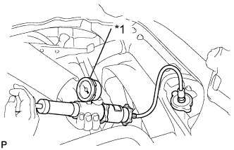
Text in Illustration *1 Radiator Cap Tester Fill the radiator with coolant and attach a radiator cap tester.
-
Warm up the engine.
-
Pump it to 118 kPa (1.2 kgf/cm2, 17.1 psi), then check that the pressure does not drop.
If the pressure drops, check the hoses, radiator and water pump for leakage. If there are no signs of external coolant leakage, check the heater core, cylinder block and head.
-
Reinstall the radiator cap.
-
-
INSPECT FOR FUEL LEAK
-
PERFORM ACTIVE TEST
-
Connect the intelligent tester to the DLC3.
-
Turn the ignition switch ON.
-
Turn the intelligent tester ON.
-
Start the engine.
-
Enter the following menus: Powertrain / ECD / Active Test.
-
Perform the Active Test.
Intelligent Tester Display Test Details Control Range Diagnostic Notes Test the Fuel Leak Pressurizes common rail internal fuel pressure, and checks for fuel leaks Stop/Start
-
Fuel pressure inside common rail pressurized to specified value and engine speed increased to 2,000 rpm when ON is selected
-
Above conditions preserved while test is ON
-
-
Make sure that there is no fuel leakage in the fuel system during the Active Test.
-
-
-
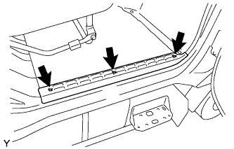
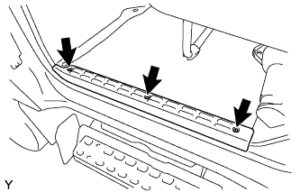
INSTALL TRANSMISSION SERVICE HOLE COVER SUB-ASSEMBLY (for Double Cab)
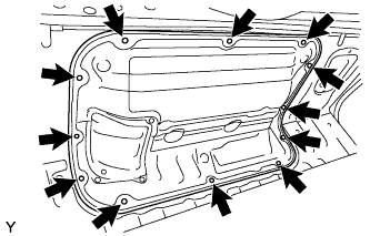
-
Install the transmission service hole cover with the 12 bolts.
-
-
INSTALL NO. 4 MAT SET PLATE (for Double Cab)
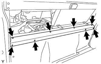
-
Install the mat set plate with the 6 screws.
-
-
INSTALL REAR FLOOR MAT (for Double Cab)
-
INSTALL REAR DOOR SCUFF PLATE LH (for Double Cab)
-
Install the rear door scuff plate with the 3 screws.
-
-
INSTALL REAR DOOR SCUFF PLATE RH (for Double Cab)
-
Install the rear door scuff plate with the 3 screws.
-