FUEL INJECTOR (w/o DPF) REMOVAL
-
CHECK FOR INJECTOR COMPENSATION CODE
-
Check that the injection compensation code of the fuel injector installed on each cylinder match the ones registered in the ECM.
If they do not match, correct the registration details. Click here
-
-
DISCONNECT CABLE FROM NEGATIVE BATTERY TERMINAL
-
REMOVE FRONT SEAT ASSEMBLY LH (for Double Cab)
-
Disconnect the connector.
-
Remove the 4 bolts and front seat LH.
-
-
REMOVE FRONT DOOR SCUFF PLATE LH (for Double Cab)
-
Remove the 4 screws and front door scuff plate LH.
-
-
REMOVE PARKING BRAKE HOLE COVER (for Double Cab)

-
Remove the screw and parking brake hole cover.
-
-
REMOVE SHIFT LEVER KNOB SUB-ASSEMBLY (for Double Cab)
-
REMOVE FRONT FLOOR PANEL BRACE (for Double Cab)
-
Remove the 3 clips, then remove the floor panel brace with the shifting hole cover.
-
-
REMOVE NO. 1 FRONT FLOOR MAT REAR (for Double Cab)
-
SEPARATE FLOOR SHIFT CABLE TRANSMISSION CONTROL SELECT (for Double Cab)
-
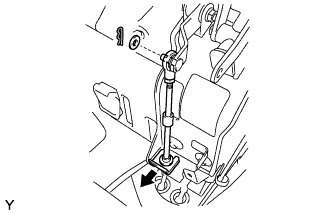
Remove the clip.
-
Remove the clip and washer, and separate the floor shift cable transmission control select.
-
-
SEPARATE FLOOR SHIFT CABLE TRANSMISSION CONTROL SHIFT (for Double Cab)
-

Remove the clip.
-
Remove the nut and washer, and separate the floor shift cable transmission control shift.
-
-
REMOVE TRANSMISSION FLOOR SHIFT ASSEMBLY (for Double Cab)
-
Remove the 4 bolts and transmission floor shift.
-
-
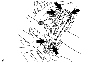
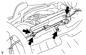
SEPARATE PARKING BRAKE LEVER ASSEMBLY (for Double Cab)
-
Disconnect the connector.
-
Remove the 4 bolts, and separate the parking brake lever with parking brake cable.
-
-
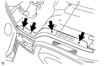
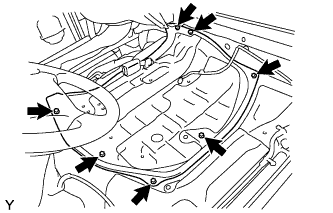
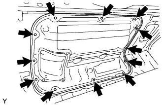
REMOVE ENGINE SERVICE HOLE SUB COVER SUB-ASSEMBLY (for Double Cab)
-
Remove the 7 bolts and engine service hole sub cover.
-
-
REMOVE REAR DOOR SCUFF PLATE LH (for Double Cab)
-
Remove the 3 screws and rear door scuff plate.
-
-
REMOVE REAR DOOR SCUFF PLATE RH (for Double Cab)
-
Remove the 3 screws and rear door scuff plate.
-
-
REMOVE REAR FLOOR MAT (for Double Cab)
-
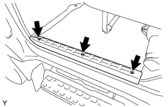
REMOVE NO. 4 MAT SET PLATE (for Double Cab)
-
Remove the 6 screws and mat set plate.
-
-
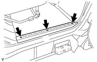
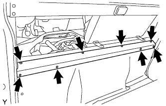
REMOVE TRANSMISSION SERVICE HOLE COVER SUB-ASSEMBLY (for Double Cab)
-
Remove the 12 bolts and service hole cover.
-
-
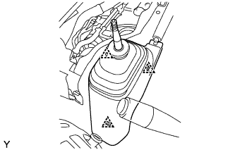
DRAIN ENGINE COOLANT
CAUTION:
To avoid the danger of being burned, do not remove the radiator cap while the engine and radiator are still hot. Thermal expansion will cause hot engine coolant and steam to blow out from the radiator.
-
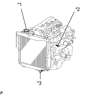
Text in Illustration *1 Radiator Cap *2 Engine Drain Plug *3 Radiator Drain Plug Loosen the radiator drain plug (on the radiator).
-
Remove the radiator cap.
-
Loosen the engine drain plug (on the oil cooler cover), and drain the coolant.
-
Drain the coolant from the reservoir tank.
-
Tighten the engine drain plug.
- Torque:
- 8.0 N*m { 82 kgf*cm, 71 in.*lbf }
-
-
REMOVE EGR COOLER ASSEMBLY
-
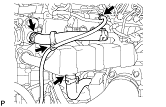
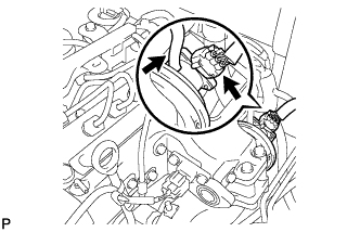
Loosen the clamp and disconnect the oil return hose.
-
Loosen the clamp and disconnect water by-pass hose No. 4.
-
Loosen the clamp and disconnect water by-pass hose No. 2.
-
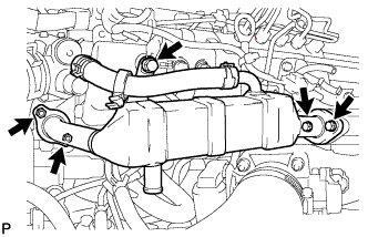
Remove the 3 bolts and 2 nuts and remove the EGR cooler assembly.
-
-
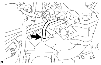
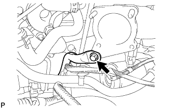
DISCONNECT NO. 3 AIR HOSE
-
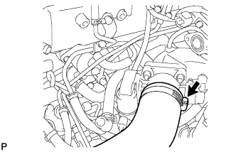
Loosen the hose clamp shown in the illustration and separate the No. 3 air hose.
-
-
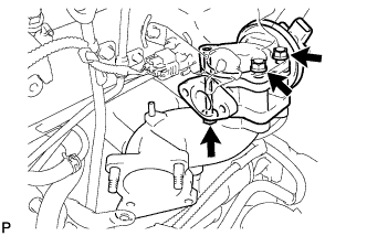
REMOVE DIESEL THROTTLE BODY
-
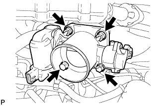
Disconnect the 2 connectors.
-
Remove the 2 nuts and 2 bolts and remove the diesel throttle body and gasket.
-
-
REMOVE ELECTRIC EGR CONTROL VALVE
-
Disconnect the vacuum regulating valve connector.
-
Disconnect the 2 vacuum hoses from the vacuum regulating valve.
-
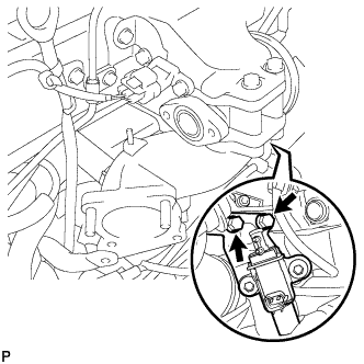
Remove the 2 bolts and remove the vacuum regulating valve with bracket.
-
Disconnect the electric EGR control valve connector.
-
Disconnect the vacuum hose from the electric EGR control valve.
-
Disconnect the vacuum hose from the intake air connector.
-
Disconnect the intake air temperature sensor connector.
-
Remove the bolt and separate the manifold stay.
-
Remove the bolt and 2 nuts, disconnect the intake air connector and remove the electric EGR control valve.
-
-
REMOVE OIL LEVEL GAGE GUIDE (for RHD)
-
Remove the oil level gage sub-assembly.
-
Remove the bolt and remove the oil level gage guide.
-
-
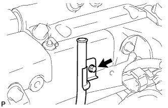
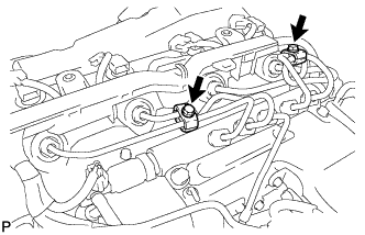
REMOVE FUEL INLET PIPE SUB-ASSEMBLY
-
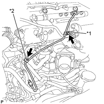
Text in Illustration *1 No. 1 Clamp *2 No. 2 Clamp Remove the bolt and remove the No. 1 injection pipe clamp.
-
Remove the bolt and remove the No. 2 injection pipe clamp.
-
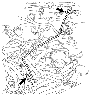
Using union nut wrench 17 mm, loosen the union nuts and remove the fuel inlet pipe sub-assembly.
-
-
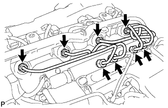
REMOVE NO. 2 NOZZLE LEAKAGE PIPE ASSEMBLY
-
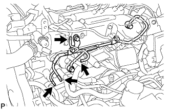
Disconnect the 4 fuel hoses from the No. 2 nozzle leakage pipe assembly.
-
Remove the 2 union bolts and 3 bolts and remove the No. 2 nozzle leakage pipe assembly.
-
-
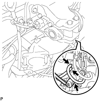
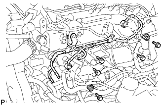
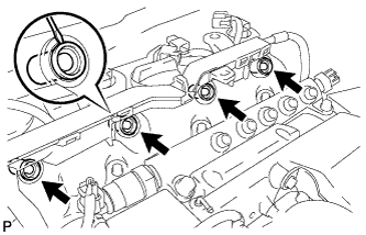
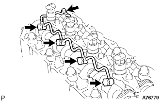
REMOVE INJECTION PIPE SUB-ASSEMBLY
-
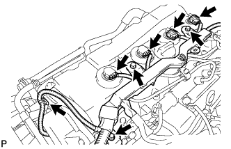
Separate the fuel injector connector and harness clamp.
-
Remove the 3 bolts and separate the wire harness.
-
Remove the 2 bolts and remove the 2 No. 2 injection pipe clamps.
-
Using union nut wrench 17 mm, loosen the union nuts and remove the 4 injection pipe sub-assemblies.
-
-
REMOVE CYLINDER HEAD COVER SUB-ASSEMBLY
-
Insert a screwdriver into the cutout of the cylinder head cover sub-assembly and remove the 4 nozzle holder seals.
-
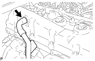
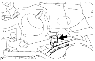
Disconnect the ventilation hose.
-
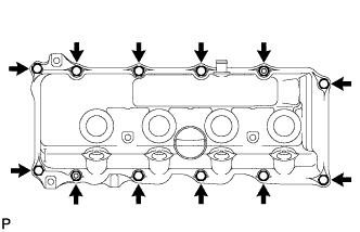
Remove the 10 bolts, 2 nuts, cylinder head cover sub-assembly and the cylinder head cover gasket.
-
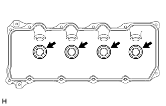
Remove the 4 No. 3 cylinder head cover gaskets from the cylinder head cover sub-assembly.
-
-
REMOVE FUEL INJECTOR
-
Remove the union bolt, 4 injector hollow screws and 5 gaskets and remove the nozzle leakage pipe assembly.
-
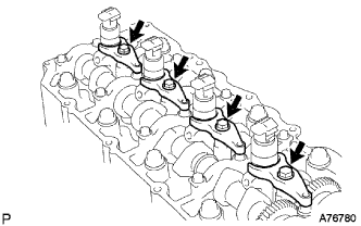
Remove the 4 bolts, 4 washers and 4 nozzle holder clamps.
Note
Keep the removed bolts and nozzle holder clamps from each cylinder in 4 separate places, one for each cylinder.
-
Remove the 4 fuel injectors.
Note
Arrange the injectors in the correct order.
-